Fault safety type current output channel diagnosis system and method
An output channel, fail-safe technology, applied in the field of electronics, which can solve the problems of easy access to danger and low diagnostic coverage.
- Summary
- Abstract
- Description
- Claims
- Application Information
AI Technical Summary
Problems solved by technology
Method used
Image
Examples
Embodiment 1
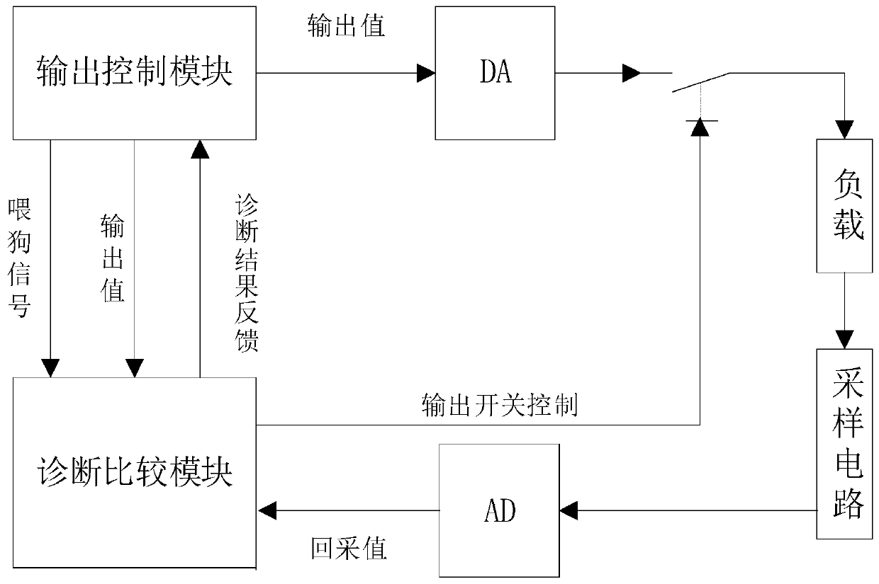
[0028] Such as figure 1 As shown, a fail-safe current output channel diagnosis system and method thereof of the present invention include an output control module, a DA module, a load, a sampling circuit, an AD module, and a diagnosis and comparison module connected in sequence, and the diagnosis and comparison module is connected to the output control module ;
[0029] The DA module and the load are connected to both ends of the switch module, and the switch module is also connected to the diagnosis comparison module;
[0030] The output control module is used to control the output current of the DA module;
[0031] The diagnosis comparison module is used for controlling the switch module and diagnosing the state of the output current, and sending the diagnosis result to the output control module.
[0032] The diagnosis comparison module also includes a WatchDog module, and the WatchDog module is used to monitor the running state of the output control module.
Embodiment 2
[0034] A fail-safe current output channel diagnosis method, the diagnosis method comprising the following steps:
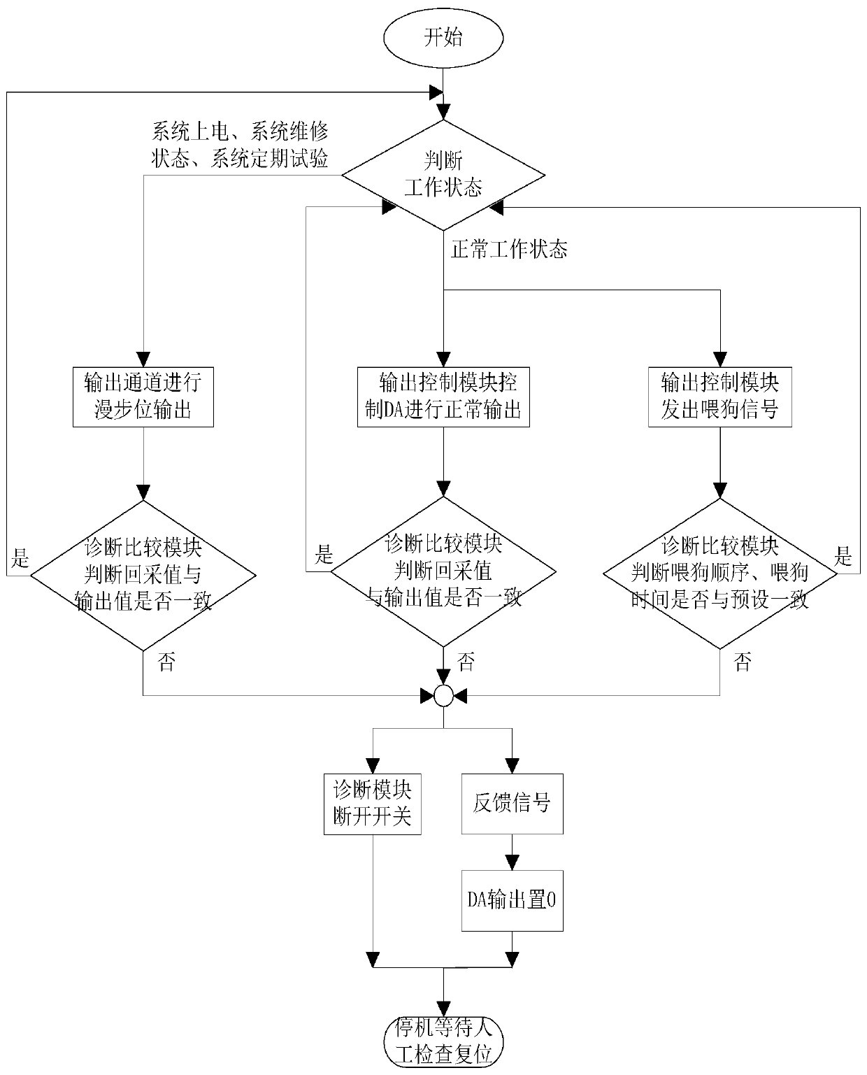
[0035] (1) The output control module controls the output current of the DA module, and the diagnostic signal enters the diagnostic comparison module through the AD module and is compared with the output value of the output control module. When a fault occurs, the diagnostic comparison module controls the switch module to disconnect;
[0036] (2) While the switch module is disconnected, the diagnosis comparison module transmits the diagnosis data to the output control module, and the output control module controls the DA module to turn off the output;
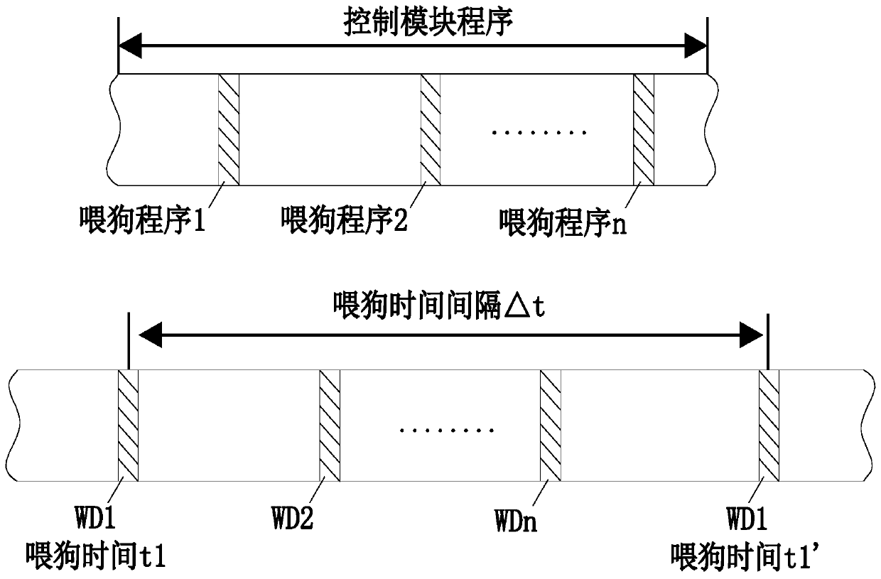
[0037] (3) The WatchDog module in the diagnosis comparison module monitors the operating state of the output control module;
[0038] (4) The order of the dog feeding signals received by the WatchDog module is the same as the preset, and the time interval between each watchdog receiving the dog signal does not excee...
Embodiment 3
[0040] On the basis of Embodiment 2, when the system is powered on, the system is in maintenance status, and the system is regularly tested, a wandering bit method is used to diagnose the current output channel. The specific operation is that the output control module will be controlled according to the method shown in Table 1. DA module output (take 10-bit SAR type DA as an example).
[0041] Table 1
[0042]
[0043]
[0044] When the system is working normally, in order not to affect the normal output, it is no longer necessary to carry out the diagnosis by walking position method, but to compare the AD recovery value of the diagnosis comparison module with the output value of the current output control module.
[0045] If the comparison results are inconsistent, the diagnosis and comparison module turns off the switch, and at the same time feeds back the diagnosis result to the output control module. The output control module controls the DA to turn off the output op...
PUM
 Abstract
Description
Claims
Application Information
 - R&D
- Intellectual Property
- Life Sciences
- Materials
- Tech Scout
- Unparalleled Data Quality
- Higher Quality Content
- 60% Fewer Hallucinations
Browse by: Latest US Patents, China's latest patents, Technical Efficacy Thesaurus, Application Domain, Technology Topic, Popular Technical Reports.
© 2025 PatSnap. All rights reserved.Legal|Privacy policy|Modern Slavery Act Transparency Statement|Sitemap|About US| Contact US: help@patsnap.com


