A magnetic wrapping wire drawing machine that is easy to combine and assemble

A combined assembly and winding wire technology, applied in the field of magnetic winding wires, can solve the problems of inconvenient magnetic ring clamping, cumbersome operation process, structural combination and fixing, etc., and achieve the effect of convenient structural combination, simple winding operation, and easy adjustment

Active Publication Date: 2022-06-24
FOSHAN MINGFUXING METAL MATERIALS CO LTD
View PDF6 Cites 0 Cited by
  • Summary
  • Abstract
  • Description
  • Claims
  • Application Information

AI Technical Summary

Problems solved by technology

[0004] The object of the present invention is to provide a magnetic winding wire drawing machine that is easy to assemble and assemble, so as to solve the problem that in the process of the existing magnetic winding wire proposed in the above-mentioned background technology, the structural combination is relatively fixed and is not easy to replace, resulting in improper clamping of the magnetic ring. Convenience, and the operation process is cumbersome, and the winding efficiency is low

Method used


Image

  • A magnetic wrapping wire drawing machine that is easy to combine and assemble
  • A magnetic wrapping wire drawing machine that is easy to combine and assemble
  • A magnetic wrapping wire drawing machine that is easy to combine and assemble

Examples


Embodiment 1

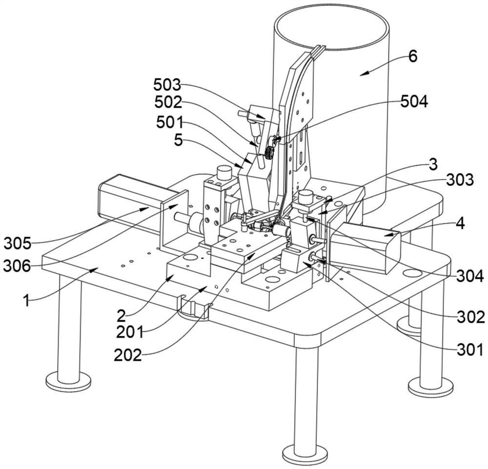
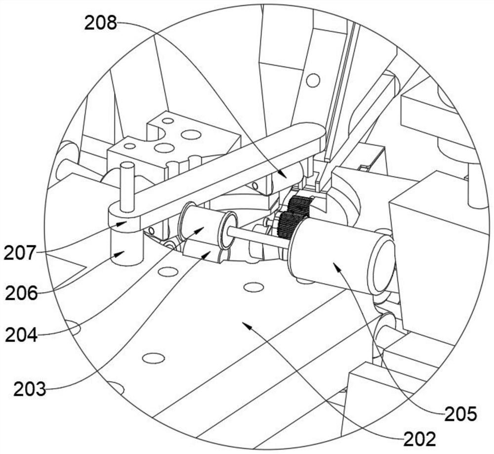
[0023] see Figure 1 to Figure 4 , an embodiment provided by the present invention: a magnetic encircling wire drawing machine that is easy to assemble 2 Including a fixed bottom block 201, a magnetic ring placing block 202, a winding sleeve 203, a sleeve transmission wheel 204, a winding transmission motor 205, a fixed sleeve 206, a height limit frame 207 and a magnetic ring limit wheel 208, the fixed bottom The magnetic ring placing block 202 is fixedly installed on the upper end surface of the block 201 by means of screw connection, the upper end surface of the magnetic ring placing block 202 is installed with a fixing sleeve 206 by means of screw connection, and the height limiter 207 is installed on the fixing sleeve 206 On the upper end face of the magnetic ring, two magnetic ring limit wheels 208 are installed at one end of the height limit frame 207. The height limit frame 207 and the magnetic ring limit wheel 208 can limit the rotation of the magnetic ring to prevent ...

Embodiment 2

[0026] On the basis of Embodiment 1, the wire drawing mechanism 5 includes a rotating movable block 501, a height adjusting rod 502, a pulley mounting frame 503, a wire tension adjusting wheel set 504, a guide angle adjusting rod 505, a bottom pulley mounting seat 506, and a guide pulley set 507 and the wire guide frame 508, a bottom pulley mounting seat 506 is installed on the outer side of the guide pulley group 507, a wire guide frame 508 is installed on one side of the bottom pulley mounting seat 506, and a guide angle adjustment rod 505 is installed on one side of the wire guide frame 508, A pulley mounting frame 503 is installed on the other side of the wire guide frame 508, a wire tension adjusting wheel group 504 is installed on one side of the pulley installation frame 503, and a height adjusting rod 502 is installed on the lower end of the pulley mounting frame 503. A rotating movable block 501 is installed on the outside, and a wire placing cylinder 6 is installed at...

Embodiment 3

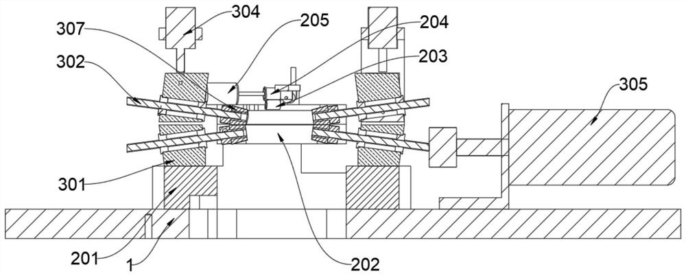
[0028]On the basis of Embodiment 2, the magnetic ring placing block 202 is fixed on the upper end surface of the fixed bottom block 201 by screw connection, the lower end of the fixing sleeve 206 is welded and fixed on the upper end surface of the magnetic ring placing block 202, and the height limit frame 207 One end is extended to the inner side of the fixed sleeve 206 through a screw connection, and the lower end surface of the height limiter 207 is connected with two magnetic ring limit wheels 208 through the connecting shaft. When the magnetic ring rotates, it is limited to prevent deviation.

[0029] The upper end surface of the magnetic ring placing block 202 is provided with a magnetic ring positioning groove, the winding sleeve 203 is arranged on the inner side of the magnetic ring positioning groove, the winding transmission motor 205 is fixed on the upper end surface of the magnetic ring placing block 202 by screw connection, and the sleeve drives The wheel 204 is f...


PUM


Abstract

The invention discloses a magnetic winding wire drawing machine which is convenient for assembly and assembly, and relates to the technical field of magnetic winding wires. In order to solve the problems that the structural combination is relatively fixed in the existing magnetic winding process, and it is not easy to replace, resulting in inconvenient clamping of the magnetic ring, cumbersome operation process, and low winding efficiency. A magnetic winding wire drawing machine that is easy to assemble and assemble, including a bottom support frame, a magnetic ring clamping mechanism is installed on the upper end surface of the bottom support frame, and the magnetic ring clamping mechanism includes a fixed bottom block and a magnetic ring placement block , winding sleeve, sleeve transmission wheel, winding transmission motor, fixed sleeve, height limit frame and magnetic ring limit wheel, the upper end surface of the fixed bottom block is equipped with a magnetic ring placement block, and the magnetic ring is placed A fixed sleeve is installed on the upper end surface of the block, and a height limiting frame is installed on the upper end surface of the fixed sleeve. The invention facilitates the adjustment of the tightness of the wire through the winding operation of the magnetic ring, and can wind the magnetic ring at one time to improve efficiency.

Description

technical field [0001] The invention relates to the technical field of magnetic wrapping wires, in particular to a magnetic wrapping wire drawing machine which is convenient for assembly and assembly. Background technique [0002] With the rapid development of society and economy, there are more and more types of electronic components. In some equipment, a magnetic ring needs to be used to protect the circuit. The magnetic ring is a ring-shaped magnetic conductor, and the magnetic ring is commonly used in electronic circuits. The anti-interference element has a good suppression effect on high-frequency noise. The magnetic ring needs to be used by winding wires on the outside of the magnetic ring before use. [0003] However, the structure combination in the existing magnetic winding process is relatively fixed and difficult to replace, resulting in inconvenient clamping of the magnetic ring, cumbersome operation process, low winding efficiency, and inability to adjust the ti...

Claims


Application Information

Patent Timeline
Patent Type & Authority Patents(China)
IPC IPC(8): H01F41/08
CPCH01F41/08
Inventor 黄家伟
Owner FOSHAN MINGFUXING METAL MATERIALS CO LTD
Why Eureka
Try Eureka