
BMU self-locking mechanism of battery system and battery pack

A battery system and self-locking technology, applied in the direction of secondary battery, battery pack components, secondary battery repair/maintenance, etc., can solve the problems of difficult installation and disassembly of BMU, inconvenient maintenance of BMS system, etc., and achieve convenient, fast and stable disassembly and assembly. , Improve the convenience and operability, the effect of easy installation and disassembly

Pending Publication Date: 2020-02-14
BEIJING PRIDE NEW ENERGY BATTERY
View PDF0 Cites 0 Cited by
  • Summary
  • Abstract
  • Description
  • Claims
  • Application Information

AI Technical Summary

Problems solved by technology

[0003] The technical problem to be solved by the present invention is that it is difficult to install and disassemble the existing BMU, which brings great inconvenience to the maintenance of the BMS system in the battery pack later.

Method used


Image

  • BMU self-locking mechanism of battery system and battery pack
  • BMU self-locking mechanism of battery system and battery pack
  • BMU self-locking mechanism of battery system and battery pack

Examples


Embodiment 1

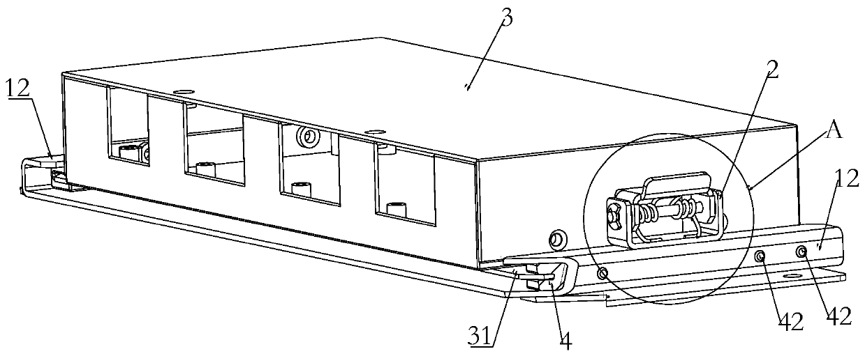
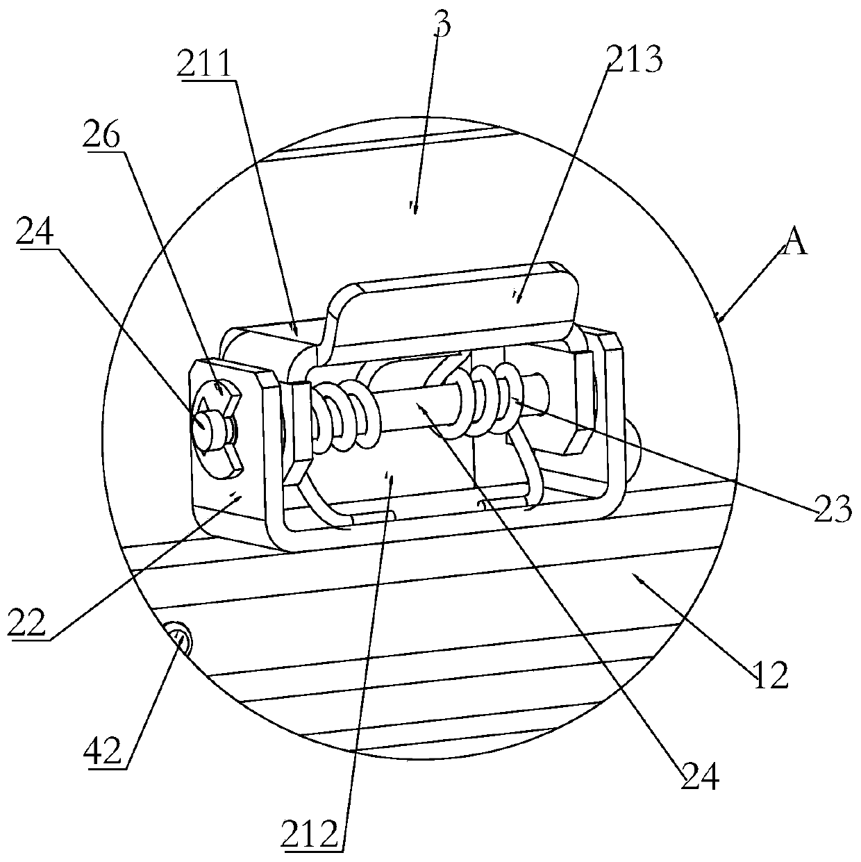
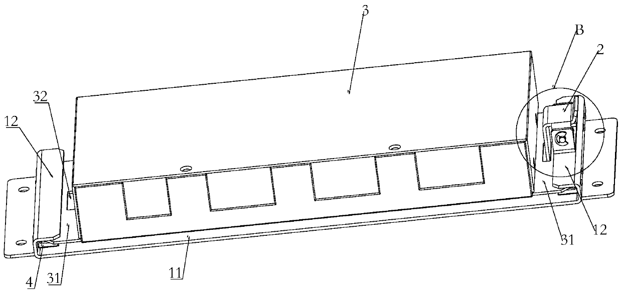
[0036] like Figure 1-Figure 5 As shown, a battery system BMU self-locking mechanism in this embodiment includes a self-locking body 1 and a locking portion 2. The self-locking body 1 is provided with two oppositely arranged slideways, and the self-locking body 1 At least one of the locking parts 2 is installed on each of the two slideways; when the BMU 3 is slidably arranged in the slideway and slid to a preset position, the locking part 2 is locked with the BMU 3 to realize the matching The limit of BMU 3 is fixed.

[0037] The self-locking mechanism of this embodiment can slide the BMU directly along the slideway of the self-locking body to a preset position, and then use the locking part to lock the BMU to achieve limit fixation of the BMU, which is easy to install and disassemble, and can realize the BMU The functions of quick disassembly and automatic locking, etc., greatly improve the convenience and operability of later maintenance.

[0038] like Figure 1-Figure 5 ...

Embodiment 2

[0052] A battery pack of the present embodiment includes the self-locking mechanism and a BMU 3. Both ends of the BMU 3 are respectively provided with a fixing plate 31 which is matched with the slideway. The locking hole 32 or the locking groove in which the locking portion 2 is matched. The locking hole 32 is preferably a rectangular through hole, and the length extending direction of the locking hole 32 is consistent with the extending direction of the slideway.

[0053] The size of the locking hole 32 or the locking groove on the fixing plate 31 is adapted to the structure of the locking portion 212 of the lock tongue 21, and there is enough space between the locking hole or the locking groove and the BMU. Space, the locking hole or the locking slot itself also reserves enough space for the disassembly and assembly of the locking part, when the locking part and the fixing plate are locked or unlocked, it can ensure that the locking part can move into or out of the locking ...


PUM


Abstract

The invention relates to a BMU self-locking mechanism of a battery system and a battery pack. The self-locking mechanism includes a self-locking main body and locking parts, wherein the self-locking main body is provided with two oppositely-arranged slideways, and at least one of the locking parts is respectively installed on the two slideways of the self-locking main body. When a BMU is slidablyarranged in the slideways and slides to a preset position, the locking parts are locked with the BMU to realize limit fixing of the BMU. By the self-locking mechanism of the invention, the BMU can directly slide to the preset position along the slideways of the self-locking main body, and then the BMU is locked through the locking parts to be limited and fixed. The self-locking mechanism is convenient to install and dismount; the functions of rapid disassembly and assembly of the BMU, automatic locking and the like can be realized; and the convenience and operability of later maintenance are greatly improved.

Description

technical field [0001] The invention relates to the technical field of power batteries, in particular to a BMU self-locking mechanism of a battery system and a battery pack. Background technique [0002] BMS (BATTERY MANAGEMENT SYSTEM) is one of the core components of the battery system. The BMS system is generally composed of multiple BMUs (Battery Management Unit). During the later operation of the battery system, the BMS often needs to collect information or upgrade the software of the BMS. The battery box is generally compact, and there is not much room for operation. The BMU is generally connected by bolts, which is difficult to disassemble. Therefore, it will cause great inconvenience to the later maintenance. SUMMARY OF THE INVENTION [0003] The technical problem to be solved by the present invention is that the existing BMU is difficult to install and disassemble, which brings great inconvenience to the maintenance of the BMS system in the battery pack in the lat...

Claims


Application Information

Patent Timeline
IPC IPC(8): H01M2/10H01M10/42
CPCH01M10/425H01M2010/4271H01M50/20Y02E60/10
Inventor 刘雪见王小龙盛力杨槐
Owner BEIJING PRIDE NEW ENERGY BATTERY
Learn More