A linear slide grinding device

A technology of linear slide rail and grinding head, which is applied in the direction of grinding drive device, grinding machine, grinding workpiece support, etc., which can solve the problems of grinding and height adjustment, and achieve the effects of reducing production costs, fixing firmly, and using safely and stably

Inactive Publication Date: 2021-04-20
湖南腾盛智能科技有限公司
View PDF6 Cites 0 Cited by
  • Summary
  • Abstract
  • Description
  • Claims
  • Application Information

AI Technical Summary

Problems solved by technology

[0003] Chinese patent (publication number: CN 108406467 A) discloses a linear slide rail grinding device, which uses eccentric gears to realize the up and down movement of the entire device, provides vertical displacement for grinding, and utilizes the rotation of the gears to drive the rotation of the grinding wheel , to provide rotation for grinding; however, the linear slide rail to be polished is fixed on the slider, and its height cannot be adjusted. Due to the long linear slide rail, it is impossible to grind all the grooves in the linear slide rail only through the eccentric gear, so , it needs to be improved to solve the above problems

Method used


Image

  • A linear slide grinding device
  • A linear slide grinding device
  • A linear slide grinding device

Examples


Embodiment 1

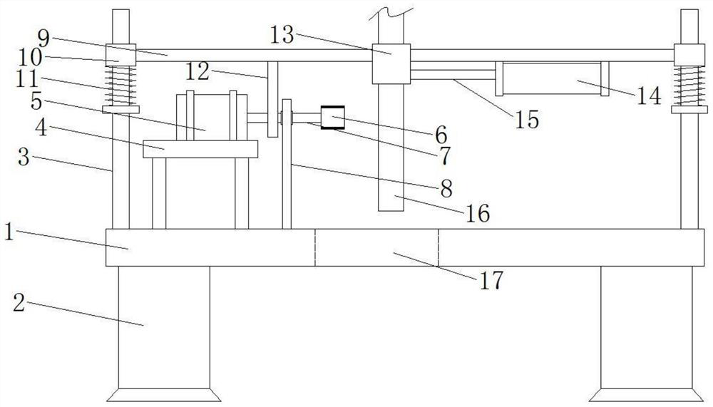
[0023] Please refer to the figure, in the embodiment of the present invention, a linear slide rail grinding device includes an operating table 1, a leg 2, a support rod 3, a motor frame 4, a grinding motor 5 and a grinding head 6; the leg 2 is fixed on The lower side of the operating table 1 is used to support the operating table 1; the motor frame 4 is fixedly installed on the upper surface of the operating table 1, and the motor frame 4 is fixedly installed with a horizontal leftward grinding motor 5. A horizontal transmission shaft 7 is coaxially fixed on the output shaft, and a grinding head 6 is installed on the other end of the transmission shaft 7, and the grinding head 6 is driven to rotate through the rotation of the grinding motor 5 to realize grinding in the groove of the linear slide rail; The shaft 7 is sleeved with a support base 8 fixed on the console 1, and the transmission shaft 7 is connected to the support base 8 through bearings to support the stable rotatio...

Embodiment 2

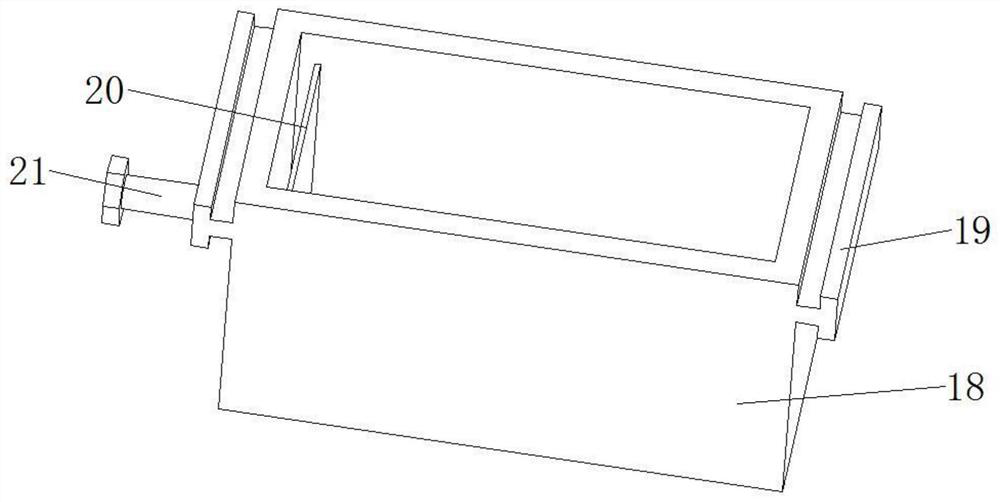
[0027] On the basis of Embodiment 1, the clamping mechanism on the adjustment mechanism 13 includes a clamping bolt 21 threaded on the side wall of the adjustment mechanism 13, and the clamping bolt 21 passes through the side wall of the adjustment mechanism 13 and extends into the Inside it, on the end of the clamping bolt 21, a splint 20 in the vertical direction is rotatably connected. There is a gap between the edge of the splint 20 and the side wall of the adjustment mechanism 13, and the distance is 1-3mm. The tightening bolt 21 is fixedly clamping the linear slide rail 16 to be polished in the adjustment mechanism 13, so as to avoid falling off during the grinding process. It wreaks havoc. On the corresponding operating platform 1 directly below the moving opening 22, there is an opening 17 that runs through the upper and lower sides. The length of the opening 17 is equal to that of the moving opening 22, so that the linear slide rail 16 to be polished placed above pass...


PUM


Abstract

The present invention relates to the field of grinding tools, and specifically discloses a linear slide grinding device, which includes an operating table, supporting legs, a support rod, a motor frame, a grinding motor and a grinding head; a horizontal lifting plate is arranged above the grinding motor , a cam that rotates eccentrically in the vertical direction is fixedly installed on the transmission shaft; a moving opening that runs through the upper and lower sides is provided on the lifting plate, and an adjusting mechanism that moves in the horizontal direction is arranged in the moving opening. There are linear slides to be ground that can be adjusted in height in the vertical direction and are fixed by clamping mechanisms. The invention drives the lifting plate to move up and down periodically through the provided cam structure, changes the grinding position of the grinding head, increases the area for one installation and grinding, and reduces the frequency of adjusting the linear slide rail to be polished; the linear slide rail can be adjusted in the vertical direction Large range, suitable for long linear slide grinding needs.

Description

technical field [0001] The invention relates to the field of grinding tools, in particular to a linear sliding rail grinding device. Background technique [0002] Linear slide rail is a kind of motion conduction guide rail that is often used in industry. Because of its low cost and convenient manufacture, it is more common in the production process. The manufacturing accuracy of linear slide rail directly determines the end execution accuracy in its application process. For In pursuit of efficiency and cost reduction, most of the linear slide rails of one model are standardized and mass-produced. After the linear slide rails are produced, there will be many small burrs, pits and protrusions in the inner holes. [0003] Chinese patent (publication number: CN 108406467 A) discloses a linear slide rail grinding device, which uses eccentric gears to realize the up and down movement of the entire device, provides vertical displacement for grinding, and utilizes the rotation of th...

Claims


Application Information

Patent Timeline
Patent Type & Authority Patents(China)
IPC IPC(8): B24B19/02B24B41/06B24B47/12B24B47/16B24B47/22
CPCB24B19/02B24B41/06B24B47/12B24B47/16B24B47/22
Inventor 邱忠炬谷依法曹利新麻新君邱实
Owner 湖南腾盛智能科技有限公司
Why Eureka
Try Eureka