

Metal mask frame surface burr removing equipment
A metal mask and burr removal technology, which is applied in metal processing equipment, grinding/polishing equipment, grinding racks, etc., can solve the problems of general grinding efficiency, achieve the effect of convenient grinding and ensure smooth progress
- Summary
- Abstract
- Description
- Claims
- Application Information
AI Technical Summary
Problems solved by technology
Method used
Image

Examples
Embodiment 1
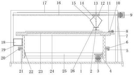
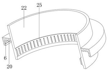
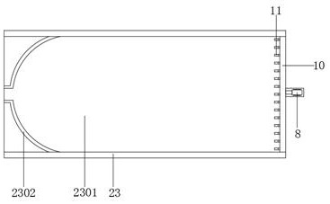
[0028] refer to Figure 1-4 , a metal mask frame surface burr removal equipment, including a base plate 1, the top outer wall of the base plate 1 is fixed with a ring support plate 21 by bolts, it is characterized in that a driven drum 22 is arranged on the top of the support ring plate 21, and The outer wall of the middle end of the driven drum 22 is welded with a side ring plate 20, and the opposite side of the side ring plate 20 and the support ring plate 21 is provided with an annular groove 6, and the inner walls of the corresponding two annular grooves 6 are rollingly connected with etc. The distance distribution balls 5, the top outer wall of the ring support plate 21 is fixed with a platen 23 by bolts, and the bottom outer wall of the platen 23 has a mounting groove, the inner wall of the mounting groove is fixed with an electromagnet 24 by bolts, and the top outer wall of the bottom plate 1 The mounting end frame is fixed by bolts, and the end of the mounting end fram...
Embodiment 2
[0040] refer to Figure 1-4, a metal mask frame surface burr removal method, which uses a metal mask frame surface burr removal equipment, the device includes a base plate 1, the top outer wall of the base plate 1 is fixed with a ring support plate 21 by bolts, and the ring support plate The top of 21 is provided with a driven drum 22, and the outer wall of the middle end of the driven drum 22 is welded with a side ring plate 20, and the opposite side of the side ring plate 20 and the ring support plate 21 is provided with an annular groove 6, and Corresponding to the inner walls of the two annular grooves 6, there are balls 5 distributed equidistantly in rolling connection. The top outer wall of the support ring plate 21 is fixed with a platen 23 by bolts, and the bottom outer wall of the platen 23 is provided with a mounting groove, and the inner wall of the mounting groove passes through Bolts are fixed with electromagnet 24, and the top outer wall of bottom plate 1 is fixe...
PUM
 Abstract
Description
Claims
Application Information