
Grinding device for mechanical accessory machining

A technology for mechanical accessories and grinding mechanisms, which is applied in the direction of grinding drive devices, grinding/polishing safety devices, metal processing equipment, etc. It can solve problems such as inability to accurately adjust the grinding angle, affect the grinding effect of accessories, and large vibration force, etc., to achieve It is convenient for fine grinding, has good shock absorption effect and reduces the effect of vibration impact

Pending Publication Date: 2021-02-23
ZHUZHOU HUAXIN PRECISION IND
View PDF10 Cites 0 Cited by
  • Summary
  • Abstract
  • Description
  • Claims
  • Application Information

AI Technical Summary

Problems solved by technology

[0002] When the mechanical parts are processed, the grinding device will be used to polish the parts, so that the parts can meet the corresponding requirements. However, the grinding device will generate a lot of vibration when grinding the parts, and there is a certain probability that it will affect the parts. The grinding effect is very good, and the existing technology cannot accurately adjust the grinding angle for fine grinding, and most of the traditional grinding devices ignore the waste chips generated when grinding accessories, the waste chips are scattered everywhere, and it is difficult to clean

Method used


Image

  • Grinding device for mechanical accessory machining
  • Grinding device for mechanical accessory machining
  • Grinding device for mechanical accessory machining

Examples


Embodiment 1

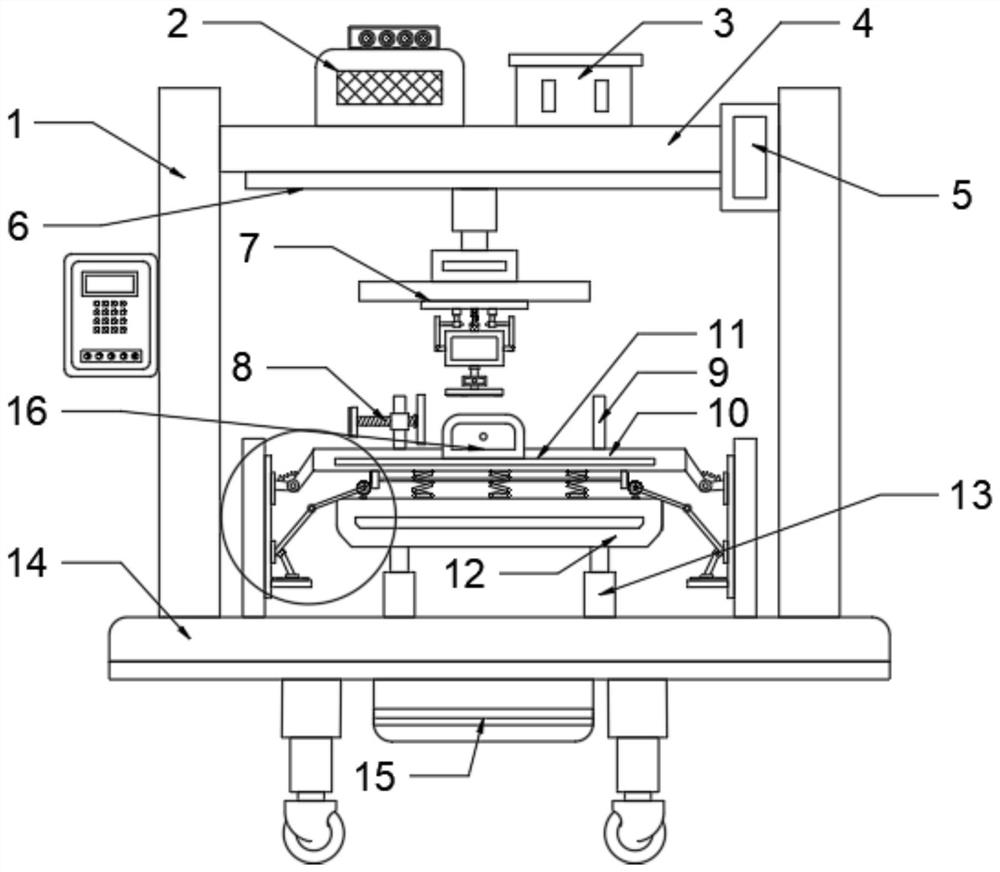
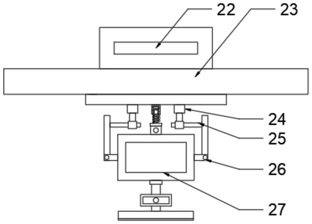
[0022] see Figure 1~4 , in an embodiment of the present invention, a grinding device for mechanical parts processing includes a base 14; a mounting frame 1 is installed on the top of the base 14; a top seat 4 is installed between the mounting frames 1; The bottom end of the seat 4 is connected to the grinding mechanism 7 through a horizontal adjustment mechanism; the top of the base 14 is provided with a placement plate 10 corresponding to the grinding mechanism 7; the placement plate 10 is provided with a clamping mechanism; the bottom of the placement plate 10 is installed There is a buffer mechanism; the placement plate 10 is connected to the fixed platform 12 through a buffer spring; the bottom of the fixed platform 12 is connected to the top of the base 14 through a hydraulic cylinder 13 .

[0023] Further, the horizontal adjustment mechanism includes No. 1 drive box 5 and slide rail 6; the No. 1 drive box 5 is installed on the top seat 4; the No. 1 drive box 5 is provid...

Embodiment 2

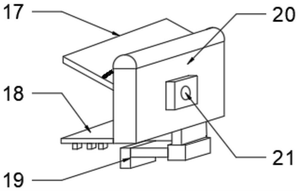
[0029] see figure 1 Or 2, a dust removal and drying mechanism 16 is installed on the placement plate 10; the dust removal and drying mechanism 16 includes a work box 20; a connector 21 is installed on one side of the work box 20; the other side of the work box 20 Pressure nozzle, waste baffle 17 and limit plate 18 are installed; Described waste baffle 17 is hinged working box 20; The top of described waste baffle 17 is connected working box 20 by spring bar; Described limit plate The bottom of 18 is equipped with a limit moving block; the top corresponding limit moving block of the placement plate 10 is provided with a limit moving groove; the connector 21 communicates with the working box 20; the connector 21 communicates with the water tank 3 through a water pipe; The connector 21 is connected to the dust removal fan 2 through the air pipe; the dust removal fan 2 is provided with a carbon fiber pipe heater; the water pipe and the air pipe are equipped with electromagnetic va...


PUM


Abstract

The invention discloses a grinding device for mechanical accessory machining, which comprises a base. Mounting frames are mounted at the top of the base; a top seat is mounted between the mounting frames; the bottom end of the top seat is connected with a grinding mechanism through a transverse adjusting mechanism; a placing plate is arranged at the top of the base and corresponds to the grindingmechanism; a clamping mechanism is arranged on the placing plate; a buffer mechanism is mounted at the bottom of the placing plate; the placing plate is connected with a fixed table through buffer springs; and the bottom of the fixed table is connected with the top of the base through a hydraulic cylinder. The grinding device for mechanical accessory machining provided by the invention can be adjusted at multiple angles, a damping effect is good, fine grinding is facilitated, a grinding effect is good, dust removal is convenient and effective, and energy is saved.

Description

technical field [0001] The invention relates to the technical field of mechanical grinding, in particular to a grinding device for machining mechanical parts. Background technique [0002] When the mechanical parts are processed, the grinding device will be used to polish the parts, so that the parts can meet the corresponding requirements. However, the grinding device will generate a lot of vibration when grinding the parts, and there is a certain probability that it will affect the parts. In order to improve the grinding effect, the existing technology cannot precisely adjust the grinding angle for fine grinding, and most of the traditional grinding devices ignore the waste chips generated when grinding accessories, and the waste chips are scattered everywhere, making cleaning difficult. [0003] Therefore, in view of the above present situation, it is urgent to develop a grinding device for mechanical parts processing. Contents of the invention [0004] The object of t...

Claims


Application Information

Patent Timeline
Patent Type & Authority Applications(China)
IPC IPC(8): B24B19/00B24B41/06B24B47/12B24B47/22B24B41/00B24B41/02B24B49/12B24B55/00B24B55/12B24B55/06B08B3/02F26B21/00
CPCB24B19/00B24B41/06B24B47/12B24B47/22B24B41/007B24B41/02B24B49/12B24B55/00B24B55/12B24B55/06B08B3/02F26B21/001
Inventor 张平雷激
Owner ZHUZHOU HUAXIN PRECISION IND
Learn More