Petrochemical transportation protection device
A protection device, petrochemical technology, applied in the directions of transportation and packaging, packaging, containers, etc., can solve the problems of easy failure, structural damage of oil storage tanks, high cost, and achieve the effect of ensuring safety, low cost and simple structure
- Summary
- Abstract
- Description
- Claims
- Application Information
AI Technical Summary
Problems solved by technology
Method used
Image
Examples
Embodiment 1
[0039] The buffer rotating plate 234 is included, and the buffer rotating plate 234 is adapted to the inside of the oil storage tank 2 and divides the inner cavity of the oil storage tank 2 equidistantly to form at least two sub-chambers.
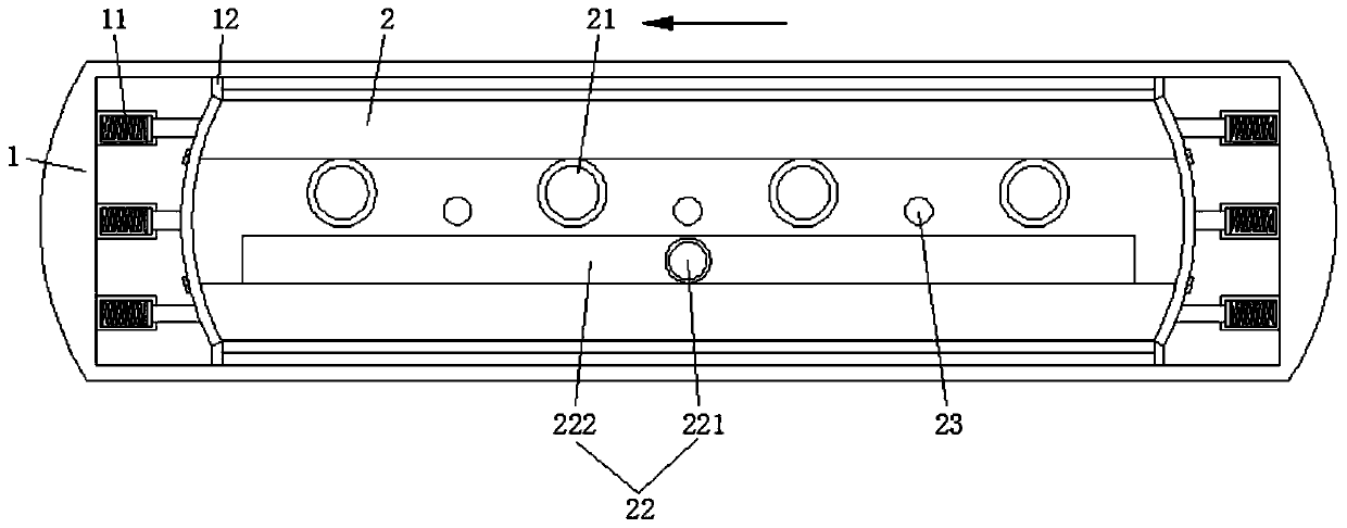
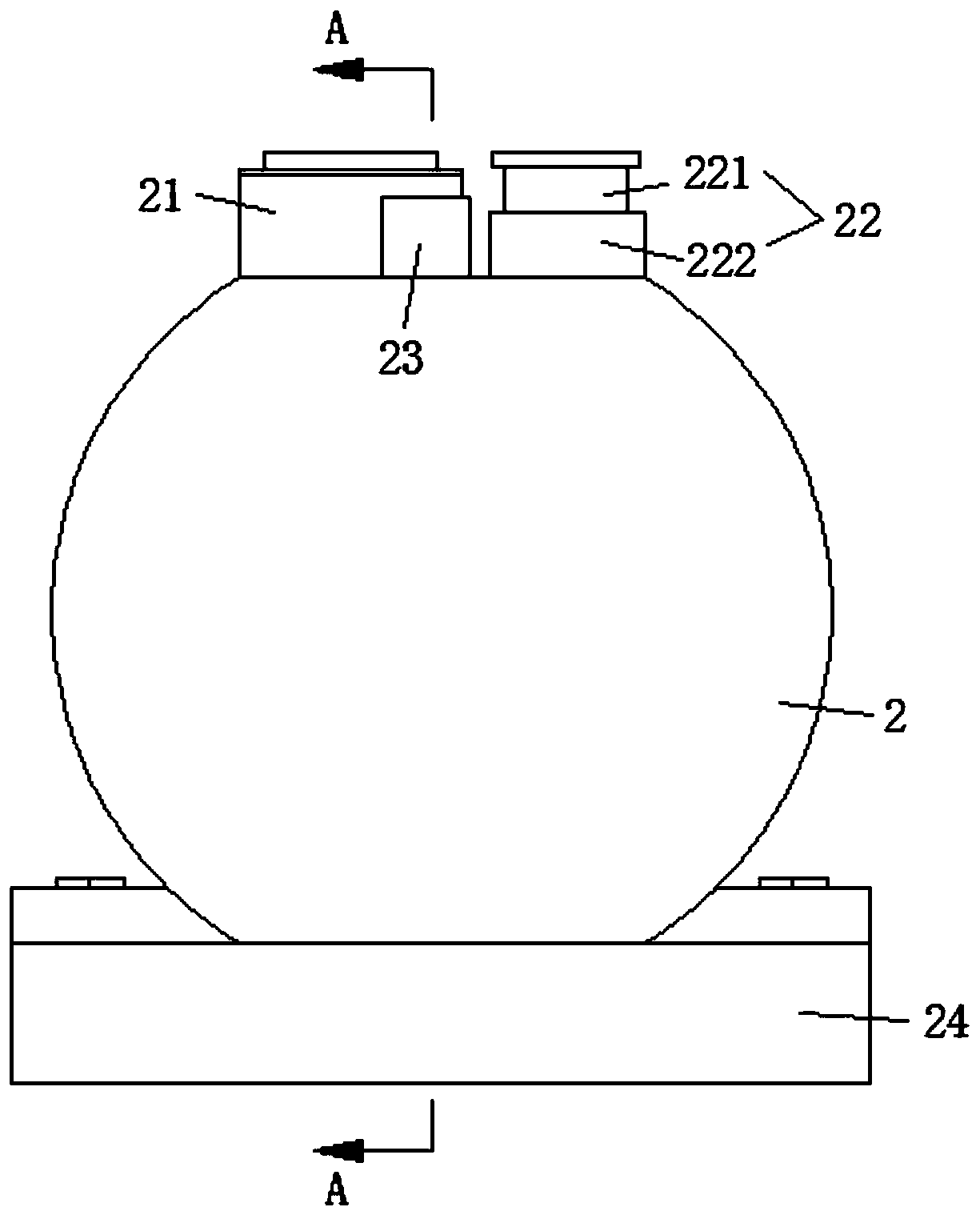
[0040] a step closer to combine figure 2 and Figure 7 , also includes an oil inlet assembly 22 and a protective base 24, wherein the oil inlet assembly 22 includes an oil inlet 221, a shunt box 222 and a shunt pipe 223 connected in sequence, and the shunt pipe 223 is connected to the sub-chamber; each sub-chamber is An oil outlet is provided, and an oil outlet is provided in the protective base 24 to form cooperation with each oil outlet.
[0041] Specifically, the petroleum products stored in the oil storage tank 2 are produced due to inertia image 3 When the impact force in the direction indicated by the middle arrow is used, the overall inertial impact force of the petroleum product is divided into four small forces based on the three...
Embodiment 2
[0043] Based on the structure of Embodiment 1, the buffer protection assembly 23 also includes a mounting sleeve 231 and a scroll spring 232, the mounting sleeve 231 is welded on the outer wall of the oil storage tank 2, and the scroll spring 232 is welded in the mounting sleeve 231; the buffer rotating plate A rotating shaft 233 vertically runs through the interior of the shaft 234 , and both ends of the rotating shaft 233 pass through the oil storage tank 2 and extend into the installation sleeve 231 to form a weld with the scroll spring 232 .
[0044] Specifically, the setting of the rotating shaft 233 makes the buffer rotating plate 234 rotate under impact, and when the buffer rotating plate 234 rotates, the rotating shaft 233 will drive the scroll spring 232 to deform, and the scroll spring 232 will generate a rebound force at this time. The above-mentioned impact is offset to weaken the direct impact on the buffer rotating plate 234 to ensure the safety and service life o...
Embodiment 3
[0046] Based on the structure in the second embodiment, the rotating shaft 233 and the buffer rotating plate 234 are arranged eccentrically, and the eccentric distance is the radius of the rotating shaft 233 .
[0047] Specifically, the purpose of the eccentric setting is to ensure that the buffering rotating plate 234 can form an effective buffering rotation when it is impacted, and the limitation of the eccentric distance is to avoid the problem that the buffering rotating plate 234 cannot separate the impact due to the excessive rotation range.
[0048] 3. Pressure control protection component 21, please refer to image 3 and Figure 5 As shown,:
[0049] It includes an exhaust pipe 212, an outer pipe 213 and a lifting cover 211 with a U-shaped cross section. An annular clamp cavity 214 is formed between the air pipes 212. The annular clamp cavity 214 is a structure with a sealed bottom and an open top, and the lifting cover 211 is buckled upside down into the annular cla...
PUM
 Abstract
Description
Claims
Application Information
 - R&D
- Intellectual Property
- Life Sciences
- Materials
- Tech Scout
- Unparalleled Data Quality
- Higher Quality Content
- 60% Fewer Hallucinations
Browse by: Latest US Patents, China's latest patents, Technical Efficacy Thesaurus, Application Domain, Technology Topic, Popular Technical Reports.
© 2025 PatSnap. All rights reserved.Legal|Privacy policy|Modern Slavery Act Transparency Statement|Sitemap|About US| Contact US: help@patsnap.com


