Adjustable well test sky pulley
An adjustable and pulley technology, applied in wellbore/well components, measurement, earthwork drilling and production, etc., can solve the problems that the trap and the instrument string cannot be separated normally, the cost of the crane tracking the well is high, and the instrument string cannot be taken out of the wellhead, etc. Achieve the effect of simple and compact overall structure, convenient height adjustment and novel design
- Summary
- Abstract
- Description
- Claims
- Application Information
AI Technical Summary
Problems solved by technology
Method used
Image
Examples
Embodiment 1
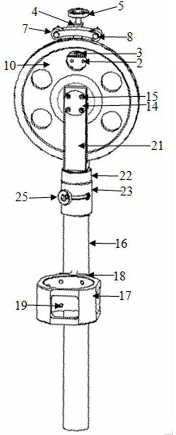
[0037] As a preferred embodiment of the present invention, with reference to the attached figure 1 , 5 and 6, this embodiment discloses:
[0038] The adjustable well test sky pulley includes an arc-shaped wire pressing assembly, a pulley assembly and a pulley bracket assembly. The pulley bracket assembly includes a mounting seat 17, an adjusting screw nut 16, an adjusting screw 22, a pulley bracket 21, and a rotation lock Sleeve 23 and bracket locking sleeve 26, the mounting seat 17 is fixedly installed on the adjustment screw nut 16, the adjustment screw 22 is hollow, one end of the pulley bracket 21 is used to install the pulley assembly, and the other end is inserted into the adjustment screw 22 And by the pulley radial bearing 20 rotating relative to the adjusting screw mandrel 22, the bracket locking sleeve 26 is packed into the adjusting screw mandrel 22 and connected with the lower end of the pulley bracket 21, and the bracket locking sleeve 26 is used to lock the lowe...
Embodiment 2
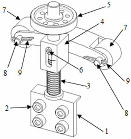
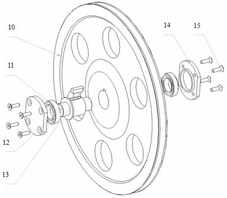
[0041] As another preferred embodiment of the present invention, with reference to the attached Figure 1-7 , this embodiment discloses:
[0042] The adjustable well test sky pulley includes an arc-shaped wire pressing assembly, a pulley assembly and a pulley bracket assembly. The pulley bracket assembly includes a mounting seat 17, an adjusting screw nut 16, an adjusting screw 22, a pulley bracket 21, and a rotation lock Sleeve 23 and bracket locking sleeve 26, the mounting seat 17 is fixedly installed on the adjustment screw nut 16, the adjustment screw 22 is hollow, one end of the pulley bracket 21 is used to install the pulley assembly, and the other end is inserted into the adjustment screw 22 And by the pulley radial bearing 20 rotating relative to the adjusting screw mandrel 22, the bracket locking sleeve 26 is packed into the adjusting screw mandrel 22 and connected with the lower end of the pulley bracket 21, and the bracket locking sleeve 26 is used to lock the lower...
Embodiment 3
[0047] As another preferred embodiment of the present invention, with reference to the attached Figure 1-7 , this embodiment discloses:
[0048] Arc-shaped wire pressing assembly: arc-shaped floating seat guide bracket 1, arc-shaped floating seat guide bracket fixing screw 2, arc-shaped floating seat guide bracket return spring 3, arc-shaped floating seat 4, arc-shaped floating seat height adjustment handwheel 5 , arc-shaped floating seat limit screw 6, wire pressing wheel 7, wire pressing wheel fixed shaft 8, and wire pressing wheel fixed shaft cotter pin 9 form.
[0049] Pulley assembly: pulley 10, pulley bearing 11, pulley shaft 12, key 13, pulley bearing gland 14, pulley bearing gland fixing screw 15 form.
[0050] Pulley bracket assembly: adjusting screw nut 16, adjusting screw nut mounting base 17, cross mounting base 18, cross mounting base fixing screw 19, pulley radial bearing 20, pulley bracket 21, external thread adjusting screw rod 22, rotation lock Cover 23, ro...
PUM
 Abstract
Description
Claims
Application Information
 - R&D
- Intellectual Property
- Life Sciences
- Materials
- Tech Scout
- Unparalleled Data Quality
- Higher Quality Content
- 60% Fewer Hallucinations
Browse by: Latest US Patents, China's latest patents, Technical Efficacy Thesaurus, Application Domain, Technology Topic, Popular Technical Reports.
© 2025 PatSnap. All rights reserved.Legal|Privacy policy|Modern Slavery Act Transparency Statement|Sitemap|About US| Contact US: help@patsnap.com


