Mounting seat for video communication equipment

A technology of video communication and mounting seat, which is applied in the direction of mechanical equipment, supporting machines, machine tables/brackets, etc. It can solve the problems of inability to adjust angles and inconvenient use by designers, and achieve easy angle adjustment, stable fixation, and safe fixation Effect

Inactive Publication Date: 2020-02-18
衡阳市和仲通讯科技有限公司
View PDF13 Cites 2 Cited by
  • Summary
  • Abstract
  • Description
  • Claims
  • Application Information

AI Technical Summary

Problems solved by technology

The LED display mounting seat device in the above-mentioned patent has the following disadvantages: During the use of the whole device, the whole device is a fixed bracket structure, and the angle cannot be adjusted, which is not convenient for designers to use

Method used


Image

  • Mounting seat for video communication equipment
  • Mounting seat for video communication equipment
  • Mounting seat for video communication equipment

Examples


Embodiment 1

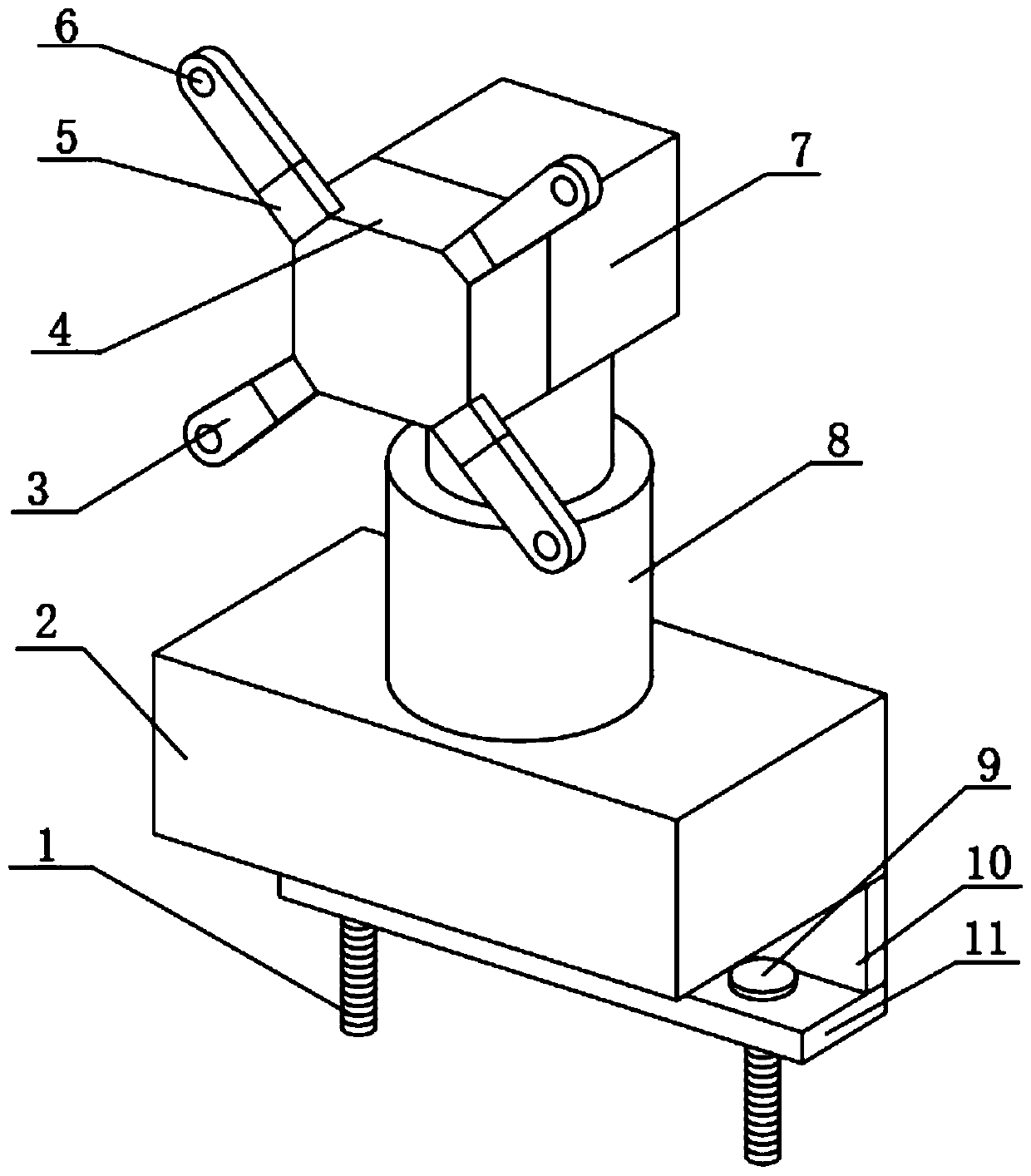
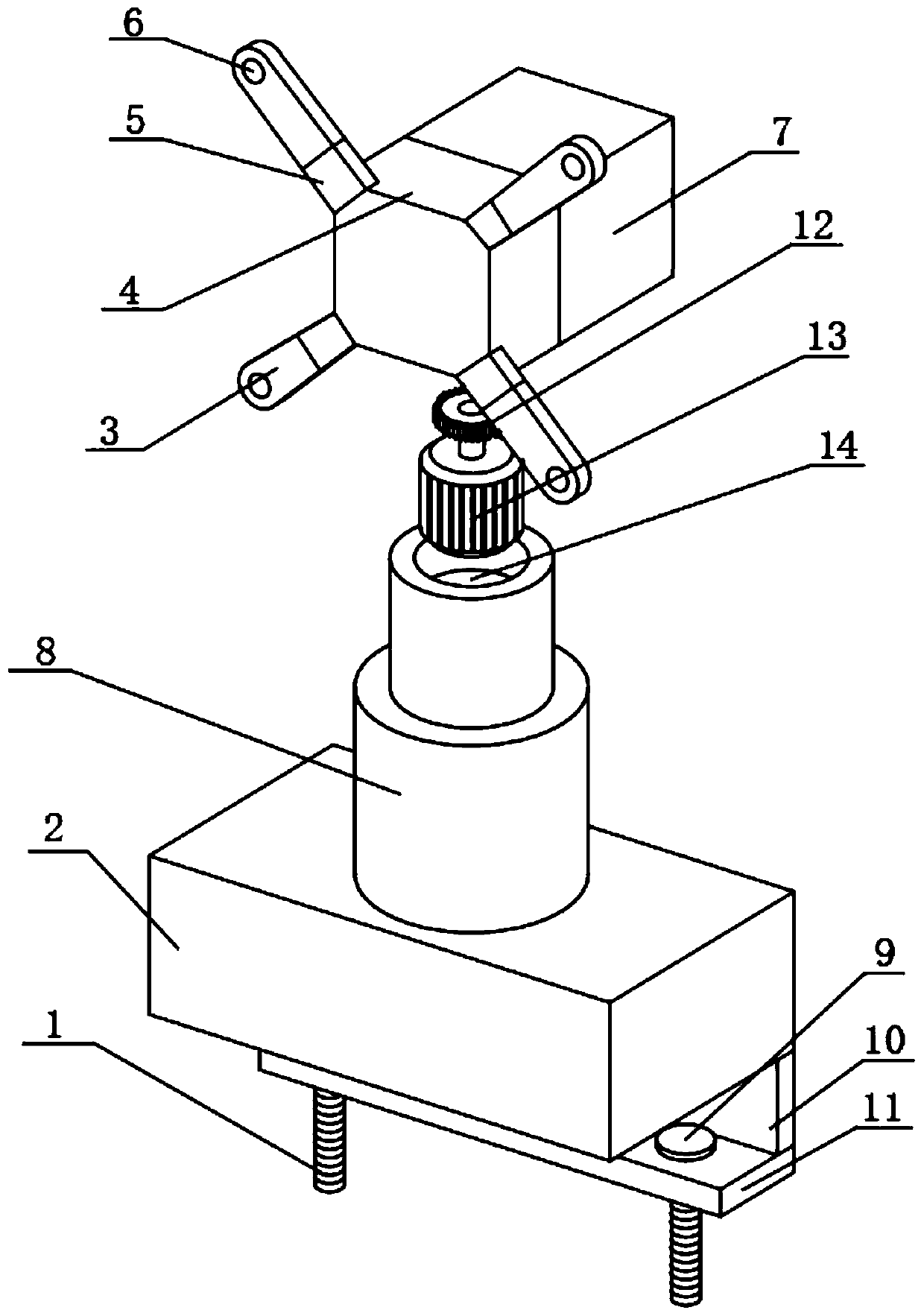
[0028] A mount for video communication equipment, such as Figure 1-3 As shown, the fixed base 2 is included, and the top of the fixed base 2 is provided with a vertically arranged first hole, and the circumferential inner wall of the first hole is sleeved with a vertically arranged electric push rod 8, and the top of the electric push rod 8 passes through the bearing The rotation socket is provided with a horizontally arranged installation base 7, and the bottom of the installation base 7 is provided with a second hole, and the circumferential inner wall of the second hole is sleeved with a gear ring 1, and the top of the electric push rod 8 is provided with a vertically arranged Motor groove one 14, the circumference inner wall of motor groove one 14 is socketed with vertically arranged motor one 13, and the output shaft of motor one 13 is socketed with horizontally arranged driving gear one 12, and driving gear one 12 and gear ring One side is meshed, and one side of the in...

Embodiment 2

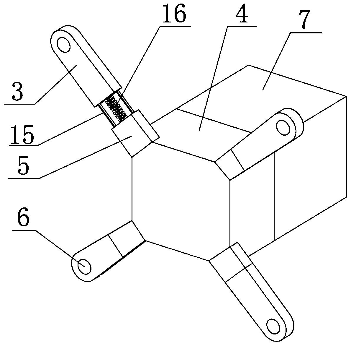
[0032] A mount for video communication equipment, such as Figure 1-4 As shown, one side of the installation base 7 is provided with a horizontal motor groove 20, and the inner wall of the motor groove 20 is sleeved with a vertical motor 19, and the output shaft of the motor 19 is socketed with The drive gear 2 17 arranged vertically, the gear ring 2 is installed on the side where the fixed plate 4 is installed, and the gear ring 2 meshes with the drive gear 2 17, and the inner wall of the fixed hole 6 is sleeved with a vertically arranged rubber gasket 18.

[0033] When this embodiment is in use, the mounting base for the video communication equipment has a hole on one side of the mounting base 7 and is equipped with a motor 2 19, and the output shaft of the motor 2 19 is meshed with the gear ring 2 through the driving gear 2 17 , it can make the mounting plate 4 on one side and the entire display screen easy to rotate, and it is more convenient to adjust the angle of the di...


PUM


Abstract

The invention discloses a mounting seat for video communication equipment, relates to the technical field of electronic products, and solves the problem that the angle of a display mounting bracket isadjusted inconveniently if being fixed. The mounting seat specifically comprises a fixed base. A vertically formed first hole is formed in the top of the fixed base, a vertically arranged electric push rod is connected to the inner wall of circumference of the first hole in a sleeving manner, a horizontally arranged mounting substrate is rotatably connected to the top of the electric push rod ina sleeving manner through a bearing, a second hole is formed in the bottom of the mounting substrate, and a gear ring I is connected to the inner wall of circumference of the second hole in a sleevingmanner. As the vertically arranged electric push rod is mounted on the top of the fixed base of the mounting seat, the hole is formed in the top of the electric push rod, an electric motor is connected in a sleeving manner, and the electric motor I is engaged to the gear ring I at the bottom of the mounting substrate on the top, a top fixed display screen can be adjusted in a lifting manner, so that the display screen rotates conveniently at left and right angles.

Description

technical field [0001] The invention relates to the technical field of electronic products, in particular to a mounting base for video communication equipment. Background technique [0002] Electronic products are related products based on electric energy, mainly including: watches, smart phones, telephones, televisions, DVD players, video recorders, camcorders, radios, tape recorders, combination speakers, CD players, computers, game consoles, mobile communication products, etc. [0003] After retrieval, the Chinese Patent Authorized Publication No. is CN208538427U, which discloses the LED display mounting seat device, including the back cover body, the rear part of the back cover body is provided with an intermediate deflector, and the intermediate deflector is set There is an intermediate flow hole, and it is characterized in that: a connection platform is provided on the peripheral side of the intermediate deflector, and an outer heat dissipation cover located outside t...

Claims


Application Information

Patent Timeline
IPC IPC(8): F16M13/02F16M11/04F16M11/08F16M11/10F16M11/12F16M11/18F16M11/28
CPCF16M11/04F16M11/08F16M11/10F16M11/12F16M11/18F16M11/28F16M13/02
Inventor 王秀国胡澜李冬平
Owner 衡阳市和仲通讯科技有限公司
Why Eureka
Try Eureka