Vehicular illumination device
A technology for lighting devices and vehicles, which is applied in signal devices, lighting and heating equipment, headlights, etc., can solve problems such as unrealizable, achieve high appearance, and achieve the effect of appearance
- Summary
- Abstract
- Description
- Claims
- Application Information
AI Technical Summary
Problems solved by technology
Method used
Image

Examples
Embodiment approach
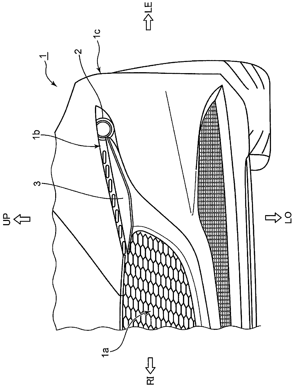
[0021] 1. Structure of vehicle front part 1a
[0022] use figure 1 The structure of the vehicle front part 1a of the vehicle 1 which concerns on embodiment is demonstrated.
[0023] Such as figure 1 As shown, in the vehicle front portion 1a of the vehicle 1, at the end in the vehicle width direction ( figure 1 The left part in the middle) is provided with a concave portion 1b that is depressed toward the rear side of the vehicle. The recessed portion 1b has an elongated shape extending in the lateral direction from the center side in the vehicle width direction toward the vehicle side portion 1c in a front view from the front of the vehicle 1 .
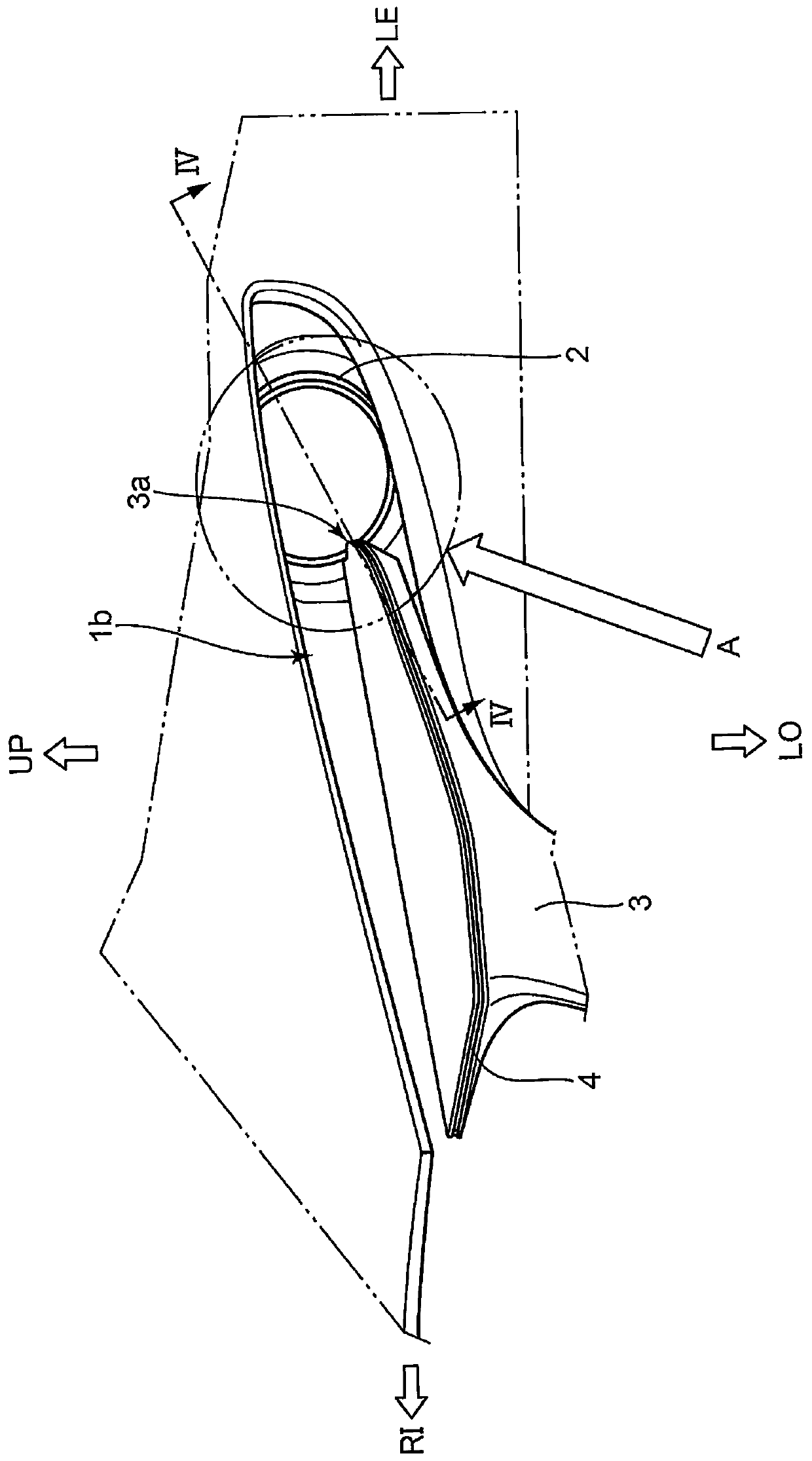
[0024] In the inner part of the recess 1b ( figure 1 The part on the back side of the page) is provided with a lighting device 2 and logo wings (registered trademark of Mazda Corporation) 3 .
[0025] The emblem wing 3 is an exterior member (garnish) that decorates the vehicle front portion 1 a of the vehicle 1 . The logo wing 3...
Deformed example 1
[0084] use Figure 9 (a) The configuration of the lighting device according to Modification 1 will be described. Figure 9 (a) is a schematic cross-sectional view showing a portion (insertion portion) where the light guide 9 and the light guide 10 face each other on the outer light transmitting member 23 in the structure of the lighting device according to this modification.
[0085] The lighting device according to this modified example adopts the same structure as the lighting device 2 according to the above-mentioned embodiment except for the part of the outer light-transmitting member 23 where the light guide 9 and the light guide 10 face each other. illustrations and descriptions.
[0086] Such as Figure 9 As shown in (a), in the outer light-transmitting member 23 according to this modification, the portion (insertion portion) facing the light guide 9 and the light guide 10 is provided with a recessed portion 23 a and a recessed portion 23 b. The concave portion 23 a ha...
Deformed example 2
[0090] use Figure 9 (b) describes the configuration of the lighting device according to Modification 2. FIG. Figure 9 (b) is a schematic cross-sectional view showing a portion (insertion portion) where the light guide 9 and the light guide 10 face each other on the outer light transmitting member 33 in the structure of the lighting device according to this modification.
[0091] The lighting device according to this modified example also adopts the same structure as the lighting device 2 related to the above-mentioned embodiment except for the part of the outer light-transmitting member 33 where the light guide 9 and the light guide 10 face each other. A diagram and description of the structure.
[0092] Such as Figure 9 As shown in (b), in the outer light-transmitting member 33 according to this modified example, an opening in the thickness direction of the outer light-transmitting member 33 is formed around the portion (insertion portion) facing the light guide 9 and th...
PUM
 Abstract
Description
Claims
Application Information
 - R&D
- Intellectual Property
- Life Sciences
- Materials
- Tech Scout
- Unparalleled Data Quality
- Higher Quality Content
- 60% Fewer Hallucinations
Browse by: Latest US Patents, China's latest patents, Technical Efficacy Thesaurus, Application Domain, Technology Topic, Popular Technical Reports.
© 2025 PatSnap. All rights reserved.Legal|Privacy policy|Modern Slavery Act Transparency Statement|Sitemap|About US| Contact US: help@patsnap.com