Electromagnetic apparatus and method for controlling fluid flow

A technology for controlling circuits and electromagnetic valves, which is applied in the direction of valve operation/release devices, valve devices, magnets, etc., and can solve problems such as armature corrosion

Active Publication Date: 2006-11-01
SLOAN VALVE COMPANY
View PDF22 Cites 18 Cited by
  • Summary
  • Abstract
  • Description
  • Claims
  • Application Information

AI Technical Summary

Problems solved by technology

This will cause problems with degradation of the armature (i.e. corrosion) and accumulation of metals and other ions (i.e. other deposits) in the lumen of the winding

Method used


Image

  • Electromagnetic apparatus and method for controlling fluid flow
  • Electromagnetic apparatus and method for controlling fluid flow
  • Electromagnetic apparatus and method for controlling fluid flow

Examples


Embodiment Construction

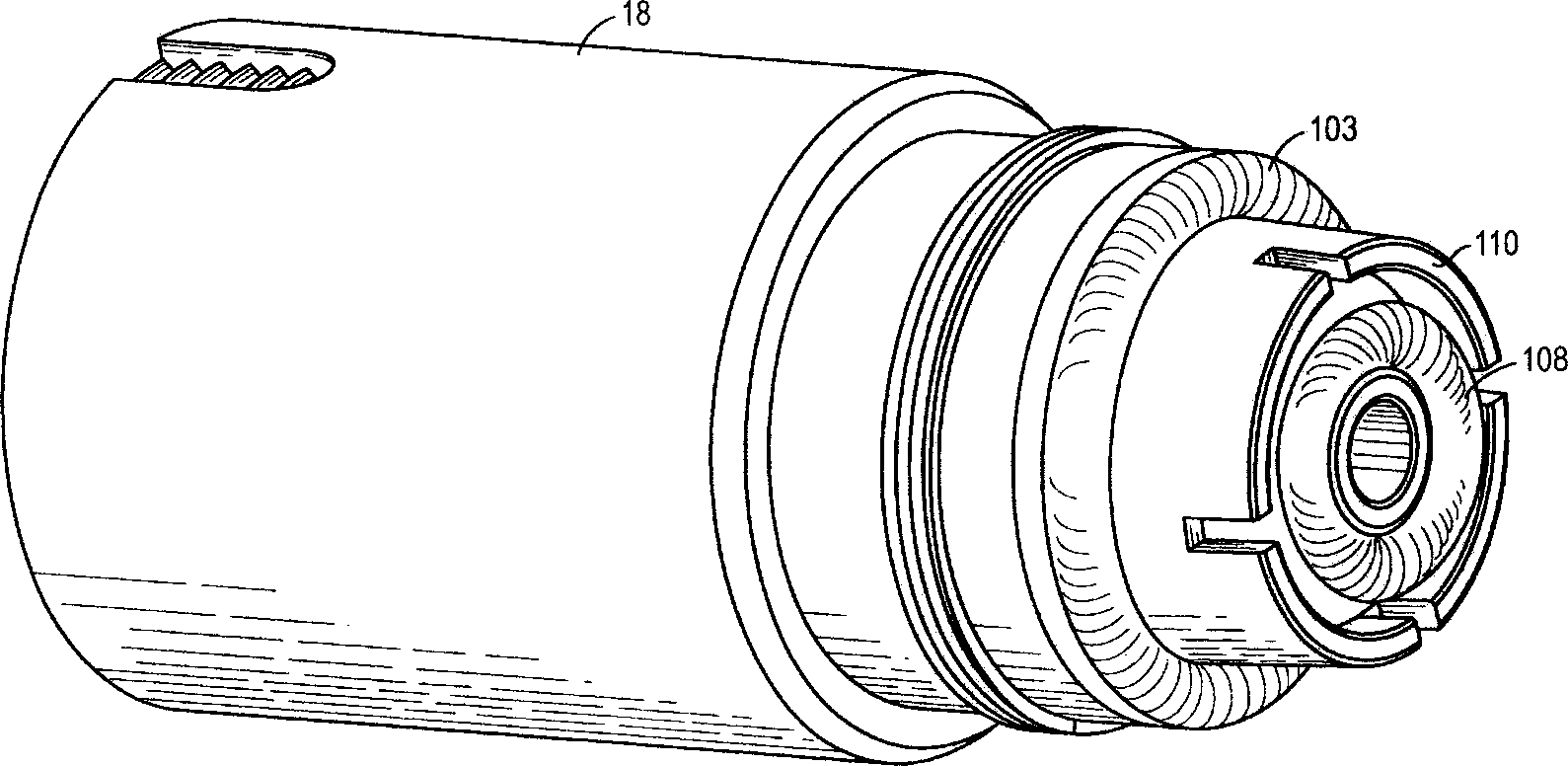
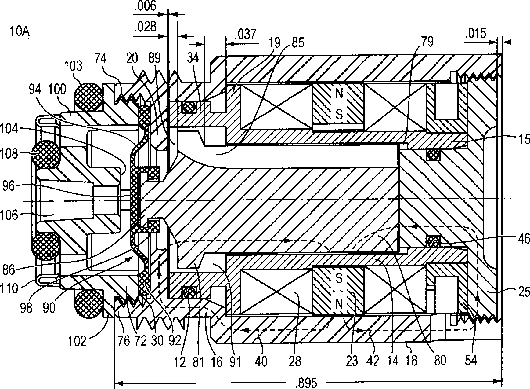
[0034] figure 1 and 2Shown is an electrically operable solenoid valve used in industrial, agricultural, and domestic systems for controlling the flow of fluids. The valve includes an electromagnetic actuator 10A that opens and closes a flow channel within the flow guide member 100 . Electromagnetic actuator 10A uses an electromagnetic field to move an armature disposed within the actuator longitudinally to and from the valve seat. The electromagnetic actuator 10A also uses the magnetic field from the radial magnets to hold the armature at the valve seat in an extended position or in a retracted position away from the valve seat, without affecting the actuator. apply any current.

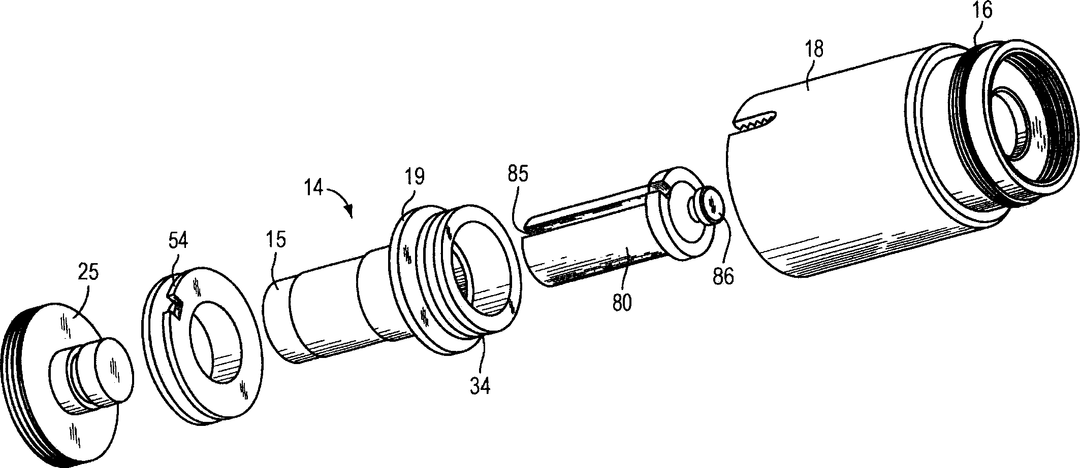
[0035] refer to figure 2 and image 3 , The electromagnetic actuator 10A includes a bobbin 14 , a cylindrical housing 18 , a rear pole piece 25 , a coil stopper 54 and an armature 80 . The armature 80 is placed within the cavity of the bobbin 14 which is placed within the cylindrical housing 1...


PUM


Abstract

An actuator including actuator base, bobbin, and pole piece forming a pocket for a ferromagnetic armature located therein. The actuator including a radial magnet and a solenoid coil. The solenoid coil is constructed and arranged to cause a linear displacement of the armature upon application of a coil drive current from a control circuit. The actuator may include a flexible membrane that partially encloses the armature to form an armature chamber filled with an incompressible fluid. In a valve design, a fluid flow is stopped by driving the armature to an extended position and thus the membrane against a valve seat. The fluid flow is opened by driving the armature and the membrane away from the valve seat into a retracted position.

Description

[0001] related application [0002] This application claims priority to US Provisional Application 60 / 659,343, filed March 5,2005. technical field [0003] This invention relates to the control of fluid flow in various systems, and more particularly to electromagnetic actuators. Background technique [0004] Various types of valves are used in industrial, agricultural and domestic systems to control the flow of liquids. The most common form of electrically operated valve employs a solenoid wound on a bobbin with a valve member placed within the bobbin and actuated by a drive current through the solenoid. In a closed position, the tip of the valve member (armature) presses against the valve seat and thereby stops the flow of liquid through the conduit at the location of the valve seat. In most cases the tip of the valve part is made of synthetic resin, or made of other elastic materials, while the rest of the valve part is made of a material with relatively high magnetic pe...

Claims


Application Information

Patent Timeline
Patent Type & Authority Applications(China)
IPC IPC(8): F16K7/14F16K31/06
CPCF16K31/082F16K7/14F16K31/0679H01F7/1615H01F7/1844
Inventor 凯·赫贝特内坦·E·佩尔松莫小雄法提赫·古勒尔
Owner SLOAN VALVE COMPANY
Why Eureka
Try Eureka