A hybrid magnetic steel AC excitation memory motor

A memory motor, AC excitation technology, applied to synchronous motors with stationary armatures and rotating magnets, magnetic circuits characterized by magnetic materials, magnetic circuits, etc., can solve the problems of increasing the copper consumption of the motor and reducing the efficiency of the motor , to achieve the effect of improving motor efficiency, increasing high-order harmonics and output capacity, and reducing electric excitation loss

Active Publication Date: 2021-01-15
NANJING UNIV OF AERONAUTICS & ASTRONAUTICS
View PDF8 Cites 0 Cited by
  • Summary
  • Abstract
  • Description
  • Claims
  • Application Information

AI Technical Summary

Problems solved by technology

However, applying a continuous field current in the AC field winding must also increase the copper loss of the motor and reduce the efficiency of the motor

Method used


Image

  • A hybrid magnetic steel AC excitation memory motor
  • A hybrid magnetic steel AC excitation memory motor
  • A hybrid magnetic steel AC excitation memory motor

Examples


Embodiment 1

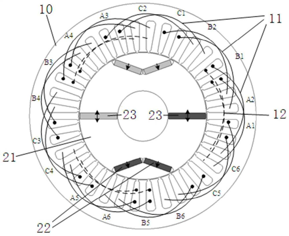
[0049] Example 1 With three-phase inner rotor m=3, N s =36, p =3i (i=1) as an example

[0050] Three-phase main winding m=3, number of stator slots N s =36, the number of pole pairs of the main winding p =3, the number of pole pairs of pulse excitation winding i=1. The phase numbers of the main winding and the pulse excitation winding can also be different.

[0051] In this embodiment, the main windings are A, B, and C phases, and the A phase can be formed by connecting A1-A6 coils in series, or can be connected in parallel by A1-A2, A3-A4, and A5-A6 respectively. Phase B and C And so on. The AC pulse excitation windings are X, Y, and Z phases. Only the X phase is shown in the figure, and the X, Y, and Z phases are counterclockwise sequentially with a difference of 120°.

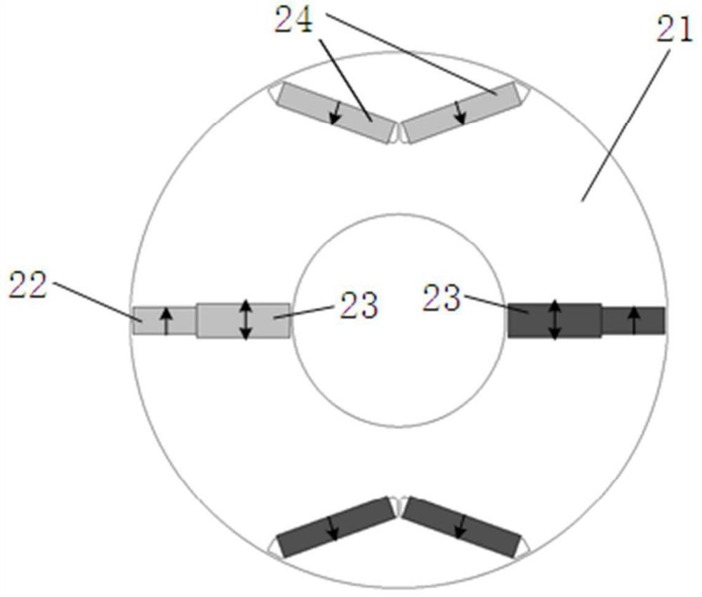
[0052] When p=3i, the number of high coercivity magnets is 2i groups, and the number of built-in tangential magnets is 2i. In this embodiment 1, the number of high coercivity magnets and built-in ta...

Embodiment 2

[0067] When p=2i, and i>1, the number of high-coercivity magnets is 2i groups, and the number of built-in tangential magnets is i.

[0068] The i built-in tangential magnets are uniformly arranged along the circumferential direction of the rotor core, and the magnetization directions of two adjacent built-in tangential magnets are the same along the circumferential direction. A pair of adjacent high-coercivity magnets with opposite polarities is arranged between two adjacent built-in tangential magnets, and an iron core is formed between a group of high-coercivity magnets and an adjacent built-in tangential magnet pole.

[0069] Such as Figure 4 As shown, the figure shows a schematic diagram of the structure when p=2i and i=2.

Embodiment 3

[0071] When p=5i, the number of high coercivity magnets is 4i groups, and the number of built-in tangential magnets is 2i. The 2i built-in tangential magnets are uniformly arranged along the circumferential direction of the rotor core, and the magnetization directions of two adjacent built-in tangential magnets are opposite along the circumferential direction. Two high-coercivity magnets with the same polarity are set between two adjacent built-in tangential magnets, and the high-coercivity magnets and adjacent built-in tangential magnets and the adjacent two high-coercivity magnets An iron core pole is formed between the coercive magnetic steels.

[0072] Such as Figure 5 As shown, the schematic diagram of the structure when p=5i and i=1 is shown in the figure.


PUM


Abstract

The invention discloses a hybrid magnetic steel alternating-current excitation memory motor. An alternating-current main winding and a pulse excitation winding for applying instantaneous pulse alternating current are wound on the stator; the rotor comprises high-coercivity magnetic steels, built-in tangential magnetic steels and iron core poles; the built-in tangential magnetic steel comprises a low-coercivity magnetic steel; the rotor has p-order high-order harmonics and i-order low-order harmonics; the number of pole pairs of the main winding is equal to the number p of high-order harmonics;the number of pole pairs of the pulse excitation winding is equal to the number i of low-order harmonics; when p is equal to 2i and i>1, the high-coercivity magnetic steels is divided into 2i groups,and the number of the built-in tangential magnetic steels is i; when p is equal to 3i, the number of the high-coercivity magnetic steels and the number of the built-in tangential magnetic steels areboth 2i; and when p is equal to 5i, the high-coercivity magnetic steels is divided into 4i groups, and the number of the built-in tangential magnetic steels is 2i. By changing the magnetization stateof the low-coercivity tangential magnetic steel, the components of the working harmonic of the rotor are changed, and on-line magnetic adjustment is realized. Due to the instantaneous pulse current, the electro-magnetic loss is very low, and the motor efficiency is improved.

Description

technical field [0001] The invention relates to the field of motor design and manufacture, in particular to a hybrid magnetic steel AC excitation memory motor. Background technique [0002] Permanent magnet motors have the advantages of high torque / power density, high efficiency and high power factor, and have been applied in many occasions. However, field weakening of PM motors is achieved by controlling the direct axis current component in the armature winding (- i d ) to achieve, the permanent magnet has the risk of irreversible demagnetization, and the weakening capacity is limited. [0003] Due to the existence of the rotor DC excitation winding, the air gap magnetic field of the electrically excited synchronous motor is easy to adjust. However, the rotor is a rotating body, and brushless DC excitation of the rotor is complicated. Therefore, the electric excitation synchronous motor needs an additional exciter to realize brushless excitation, which increases the com...

Claims


Application Information

Patent Timeline
Patent Type & Authority Patents(China)
IPC IPC(8): H02K1/27H02K1/02H02K1/16H02K21/04H02K21/12
CPCH02K1/02H02K1/16H02K1/274H02K1/2786H02K21/046H02K21/12H02K2213/03
Inventor 李健王凯张国豪孔金旺刘闯
Owner NANJING UNIV OF AERONAUTICS & ASTRONAUTICS
Why Eureka
Try Eureka