Eureka AIR delivers breakthrough ideas for toughest innovation challenges, trusted by R&D personnel around the world.

Micro thread linear motor based on magnetostrictive effect

A technology of magnetostrictive and linear motors, which is applied in the field of drive motors and micro-threaded linear motors. It can solve the problems of high drive voltage, low efficiency, and small deformation of piezoelectric materials, and achieve low drive voltage, high efficiency, and deformation. big effect

Inactive Publication Date: 2015-05-20
SHANGHAI JIAOTONG UNIV
View PDF4 Cites 0 Cited by
  • Summary
  • Abstract
  • Description
  • Claims
  • Application Information

AI Technical Summary

Problems solved by technology

It has the outstanding advantages of high displacement resolution, no noise, small size, and fast response, but piezoelectric ultrasonic motors have disadvantages such as small deformation of piezoelectric materials, high driving voltage, and low efficiency.

Method used


Image

  • Micro thread linear motor based on magnetostrictive effect
  • Micro thread linear motor based on magnetostrictive effect
  • Micro thread linear motor based on magnetostrictive effect

Examples


Embodiment 1

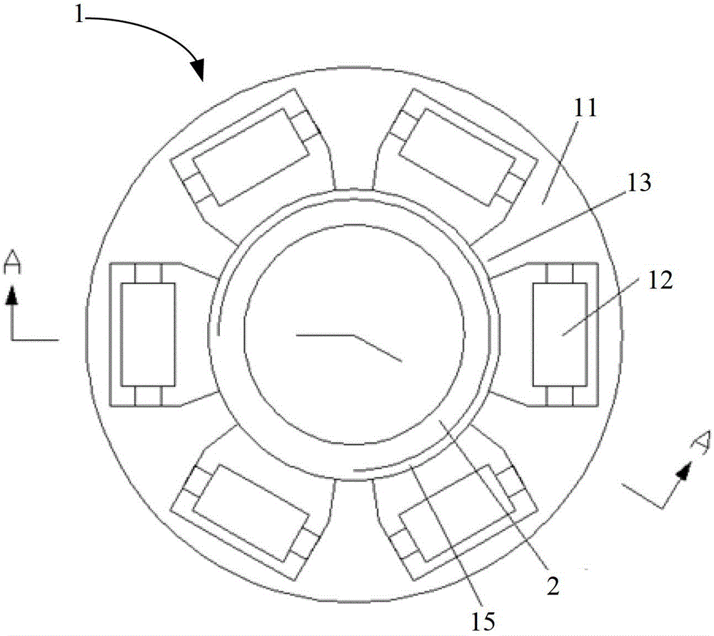
[0030] Such as figure 1 As shown, the threaded linear motor based on the magnetostrictive effect of the present embodiment includes a stator 1, a rotor 2 and an end cover 3, and the stator 1 includes a stator base 11 and 6 giant magnetostrictive units 12, and the stator base 11 is provided with 6 The giant magnetostrictive unit 12 is respectively arranged in each groove, and the protruding part between each two adjacent grooves forms a driving foot 13, and the inside of the stator base is provided with a screw thread 15, and the top is uniformly provided with 6 third grooves. Two threaded holes 14. The interior of the rotor 2 is a hollow structure, on which a thread pair 21 is arranged, which penetrates through the center of the stator base 11 and is threadedly connected with the stator base 11 through the thread 15 and the thread pair 21, and the end cover 3 adopts a ring sheet, which is connected to At the bottom of the stator base 11, six first threaded holes 31 are unifor...

Embodiment 2

[0039] see Figure 8 , in this embodiment, the stator 1 includes a stator base 11 and four giant magnetostrictive units 12, the stator base 11 is provided with four grooves, and the giant magnetostrictive units 12 are respectively arranged in each groove. When the motor is excited, along the clockwise direction, the first two giant magnetostrictive units sequentially apply two-phase sinusoidal excitation signals with a phase difference of π / 2 or negative π / 2, and the two-phase excitation signals of the last two giant magnetostrictive units The signals are in turn identical to the previous two-phase excitation signals. Except for the difference between the above and the first embodiment, and the number of the corresponding driving feet, the number of the first threaded hole and the number of the second threaded hole are all four, other components and compositions of this embodiment are the same as those of the first embodiment , which will not be described here.

[0040] Comb...


PUM


Abstract

The invention relates to a micro thread linear motor based on magnetostrictive effect. The micro thread linear motor comprises a stator, a rotor and an end cover, wherein the stator comprises a stator base body and a plurality of magnetostrictive units. A plurality of grooves are arranged on the stator base body, the magnetostrictive units are arranged in the groove, the rotor penetrates through the center of the stator base body to be in threaded connection with the stator base body, and the end cover is connected to the bottom of the stator base body. Each magnetostrictive unit comprises a super-magnetostrictive rod, a coil support, an exciting coil and a seal cover, wherein two ends of the super-magnetostrictive rod are fixedly connected into the groove of the stator base body, the middle of the super-magnetostrictive rod is provided with a boss, the coil support is connected with the boss, the exciting coil and the coil support are in wrapping connection with each other, and the seal cover is arranged on the outer side of the exciting coil and is connected with the coil support. The micro thread linear motor has the advantages of being high in precision, compact in structure, wide in frequency response, large in deformation, low in driving voltage, high in load capacity and high in efficiency, working reliably in a long time and the like, and can be widely applied to the fields of robots, medical devices, precise instruments and optics and the like.

Description

technical field [0001] The invention relates to a driving motor, in particular to a miniature threaded linear motor based on the magnetostrictive effect, which belongs to the application field of giant magnetostrictive materials. Background technique [0002] In today's world, science and technology are changing with each passing day, and more and more occasions need to use micro precision motors, such as aerospace, robotics, precision medical equipment, bioengineering and other fields. It is used in tiny and fine structures; in addition, the shortcomings of excessive backlash, inability to reduce noise, and low efficiency also limit its application. [0003] In order to overcome the above-mentioned shortcomings of the traditional electromagnetic motor, an ultrasonic motor based on the piezoelectric principle has been developed. The ultrasonic motor based on the piezoelectric principle is a kind of friction-driven motor based on the principle of vibration. It uses piezoelec...

Claims


Application Information

Patent Timeline
Patent Type & Authority Patents(China)
IPC IPC(8): H02N2/02H02N2/04
Inventor 鹿存跃竺春祥
Owner SHANGHAI JIAOTONG UNIV
Why Eureka
Eureka Blog
Learn More