
Positron CT device

A technology of positron and photon detectors, which is applied in computerized tomography scanners, echo tomography, etc., and can solve problems such as inconstant detection sensitivity of photon detectors

Pending Publication Date: 2020-02-21
SHIMADZU SEISAKUSHO CO LTD
View PDF11 Cites 0 Cited by
  • Summary
  • Abstract
  • Description
  • Claims
  • Application Information

AI Technical Summary

Problems solved by technology

[0003] The detection sensitivity of the photon detector used in such a positron CT device is not constant

Method used


Image

  • Positron CT device
  • Positron CT device
  • Positron CT device

Examples


Embodiment Construction

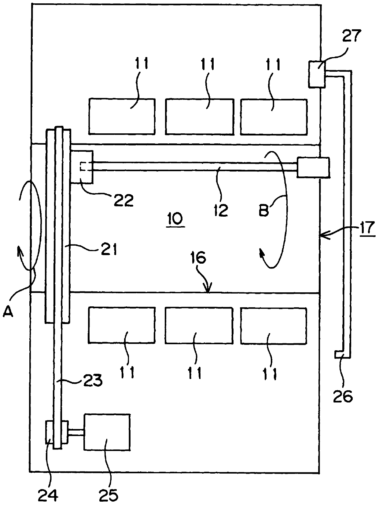
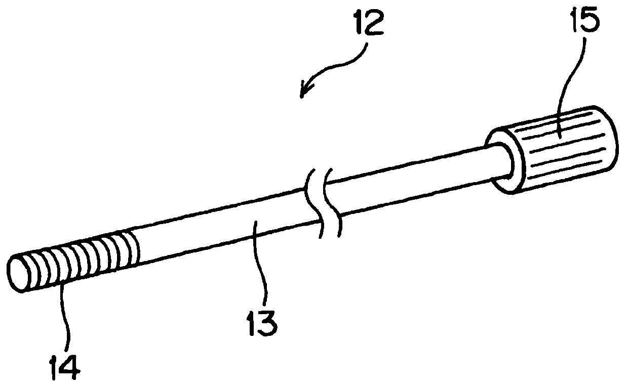
[0029] Hereinafter, embodiments of the present invention will be described based on the drawings. figure 1 It is a schematic diagram of the positron CT apparatus of the present invention. in addition, figure 2 It is a perspective view of the radiation generating member 12 used in the positron CT apparatus of the present invention.

[0030] In this positron CT apparatus, for example, the head of a subject into which radiopharmaceuticals have been administered in advance is arranged in the examination space 10 having a cylindrical shape, and pairs of annihilation photons radiated from the head of the subject are detected, thereby Acquire PET images.

[0031] This positron CT apparatus has a configuration in which photon detectors 11 for detecting radiation are arranged in a ring shape surrounding an inspection space 10 . The photon detector 11 arranged in a ring is in figure 1 In the illustrated embodiment, three columns are arranged, and the inspection space 10 is surrou...


PUM


Abstract

The present invention provides a positron CT device capable of maintaining a large inspection space and safely performing correction of the detection sensitivity of a photon detector. The positron CTdevice has a structure in which a photon detector (11) for detecting radiation is arranged in a ring shape so as to surround an inspection space (10). A plurality of photon detectors (11) are coveredby the cover member (16). The cover member (16) has a shape along the surfaces of a plurality of photon detectors (11) arranged in a ring shape, and the cover member (16) forms a cylindrical inspection space (10). The radiation generating member (12) is detachably connected to the rotating disc (21). When the rotating disc (21) rotates, the radiation generating member (12) rotates along the surface of the cover member (16) inside the inspection space (10).

Description

technical field [0001] The present invention relates to a positron CT device (Positron Emission Computed-Tomography: PET). Background technique [0002] For the positron CT apparatus, the examination area of ​​the subject into which the radiopharmaceuticals have been injected in advance is arranged in the space in the ring-shaped photon detector, and the photon detector is used to detect radiation from the examination area of ​​the subject. Pairwise annihilation photons of the radiation. And, measure the time when the photon is detected, and if the detection time difference between the two detection areas of the photon detector is within a certain time, count the photon as a pair of paired annihilation photons, and paired annihilation takes place The location is specified as the position on the line between the two detection areas where the photon was detected. The radiation data obtained in this way is stored, and image reconstruction is performed using the stored radiati...

Claims


Application Information

Patent Timeline
Patent Type & Authority Applications(China)
IPC IPC(8): A61B6/03
CPCA61B6/035
Inventor 橘一成
Owner SHIMADZU SEISAKUSHO CO LTD
Learn More