
Hot-rolled strip steel vertical roller mill machine frame rising and falling structure

A technology of vertical rolling mill and hot-rolled strip steel, which is applied in the direction of metal rolling stand, metal rolling stand, metal rolling, etc. It can solve the problems of increasing operating costs and affecting work efficiency, and achieves improved reliability and stability performance, improve utilization, and improve stability

Pending Publication Date: 2020-02-21
中重科技(天津)股份有限公司
View PDF0 Cites 0 Cited by
  • Summary
  • Abstract
  • Description
  • Claims
  • Application Information

AI Technical Summary

Problems solved by technology

The frame of the traditional vertical roller mill is directly fixed on the foundation plate, the height of the roll surface is fixed, and the height of the center line of the roll surface is aligned with the height of the rolling center line. Therefore, only a section of the center of the roll surface is used when rolling steel, and the wear of this position is bound to be very high. Large, when the wear reaches a certain level, it is necessary to replace the roll, which not only affects the work efficiency, but also greatly increases the operating cost

Method used


Image

  • Hot-rolled strip steel vertical roller mill machine frame rising and falling structure
  • Hot-rolled strip steel vertical roller mill machine frame rising and falling structure
  • Hot-rolled strip steel vertical roller mill machine frame rising and falling structure

Examples


Embodiment Construction

[0031] It should be noted that, in the case of no conflict, the embodiments of the present invention and the features in the embodiments can be combined with each other.

[0032] In describing the present invention, it should be understood that the terms "center", "longitudinal", "transverse", "upper", "lower", "front", "rear", "left", "right", The orientations or positional relationships indicated by "vertical", "horizontal", "top", "bottom", "inner", "outer", etc. are based on the orientation or positional relationships shown in the drawings, and are only for the convenience of describing the present invention Creation and simplification of description, rather than indicating or implying that the device or element referred to must have a specific orientation, be constructed and operate in a specific orientation, and therefore should not be construed as limiting the invention. In addition, the terms "first", "second", etc. are used for descriptive purposes only, and should no...


PUM


Abstract

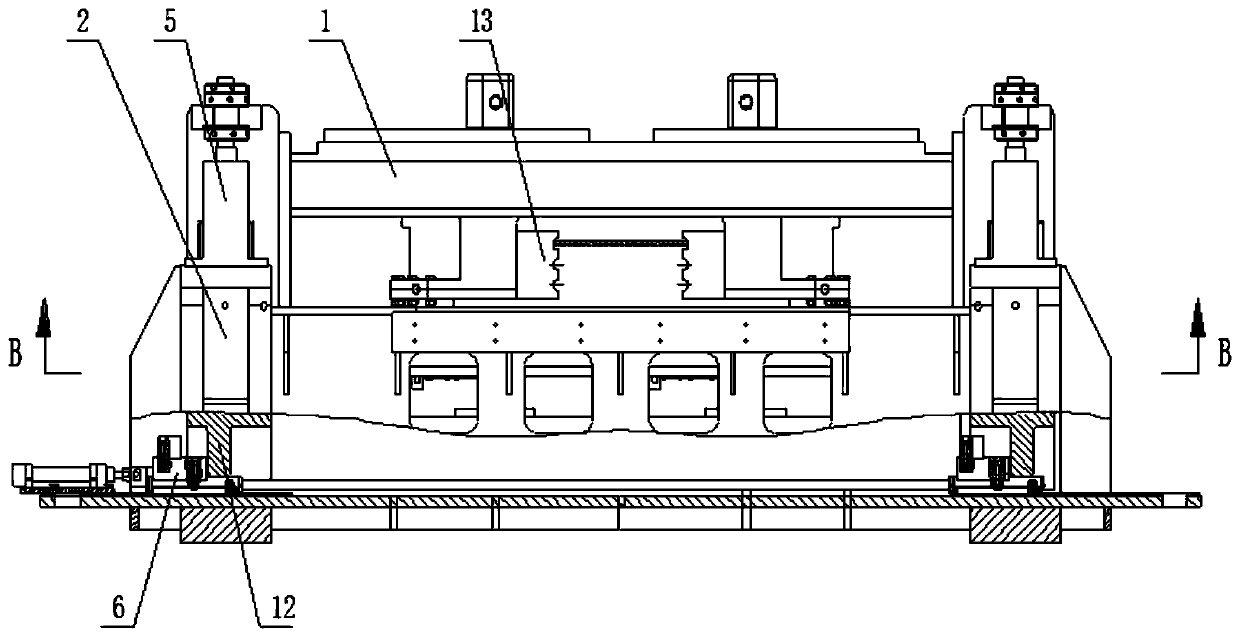
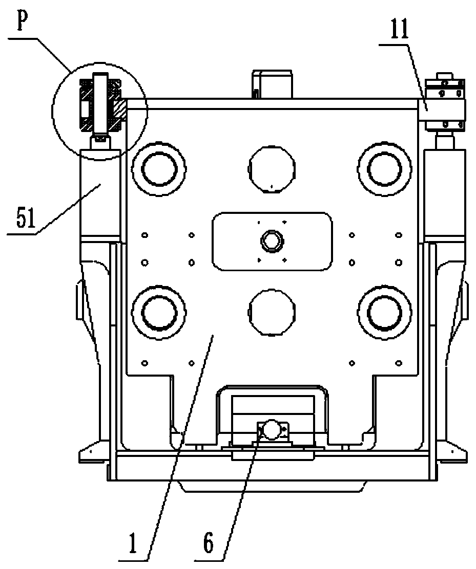
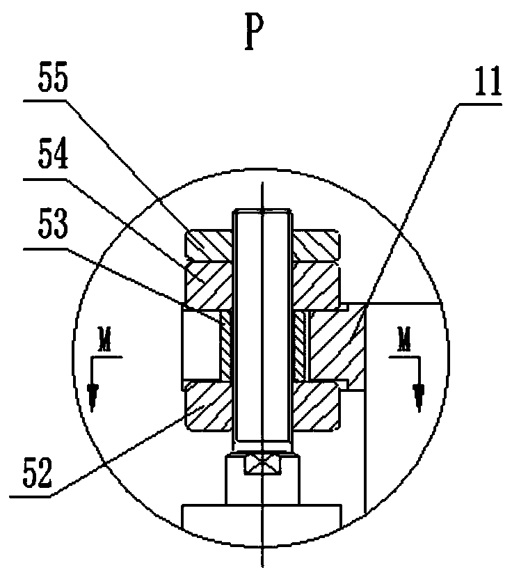
The invention provides a hot-rolled strip steel vertical roller mill machine frame rising and falling structure comprising a bearing base and a machine frame. The machine frame is vertically installedon the bearing base in a sliding manner. Rising and falling devices and adjusting devices are arranged at the position, corresponding to the machine frame, on the bearing base, wherein the rising andfalling devices and the adjusting devices are used for regulating rising and falling of the machine frame. Each rising and falling device comprises a jacking hydraulic cylinder, wherein the jacking hydraulic cylinders are arranged on the portions, corresponding to the periphery of the machine frame, on the bearing base, and connection mechanisms matched with the jacking hydraulic cylinders are arranged on the machine frame. The hot-rolled strip steel vertical roller mill machine frame rising and falling structure is simple in structure, stable and reliable, and multiple work positions can bearranged on each same roller in the height direction; by making the machine frame rise and fall, adjustment of the different work positions is achieved, and the utilization rate of the rollers is increased; by decreasing the number of roller replacement times, the rolling efficiency is improved; and meanwhile, rising and falling of the whole machine frame are achieved through the rising and falling devices, the hot-rolled strip steel vertical roller mill machine frame rising and falling structure can be suitable for changes of rolling elevations under specific conditions, and the application range of mill devices is widened.

Description

technical field [0001] The invention belongs to the field of vertical roller mill equipment for a hot-rolled strip steel production line, and in particular relates to a vertical roller mill frame lifting structure for hot-rolled strip steel. Background technique [0002] Steel plays an important role in production, construction and daily life, and most steel needs to be rolled to improve its mechanical properties, thereby enhancing its performance, so rolling equipment plays a big role. [0003] The vertical roll mill is an essential and important equipment in the hot strip steel production line. It is used to roll the strip steel in the width direction to make the strip steel width meet the requirements. There are two rollers installed on the stand of the vertical roller mill. The opening of the two rollers is set according to the rolling specifications, that is, the distance between the two roller surfaces. In order to prevent the strip from arching during rolling, it is u...

Claims


Application Information

Patent Timeline
Patent Type & Authority Applications(China)
IPC IPC(8): B21B31/02
CPCB21B31/02B21B2031/025B21B2201/06
Inventor 周乐乐
Owner 中重科技(天津)股份有限公司
Learn More