Multi-step continuous bending device of arc-shaped components

A bending device and multi-step technology, applied in the direction of feeding device, positioning device, storage device, etc., can solve the problems of inability to meet mass production, high cost, low efficiency, etc., and achieve simple and convenient bending process, forming The effect of simple process and simple structure of the bending module

Active Publication Date: 2020-02-21
CHENGDU AIRCRAFT INDUSTRY GROUP
View PDF4 Cites 2 Cited by
  • Summary
  • Abstract
  • Description
  • Claims
  • Application Information

AI Technical Summary

Problems solved by technology

This processing method has long cycle, low efficiency and high cost, and cannot meet the needs of modern industrialized mass production.

Method used


Image

  • Multi-step continuous bending device of arc-shaped components
  • Multi-step continuous bending device of arc-shaped components
  • Multi-step continuous bending device of arc-shaped components

Examples


Embodiment 1

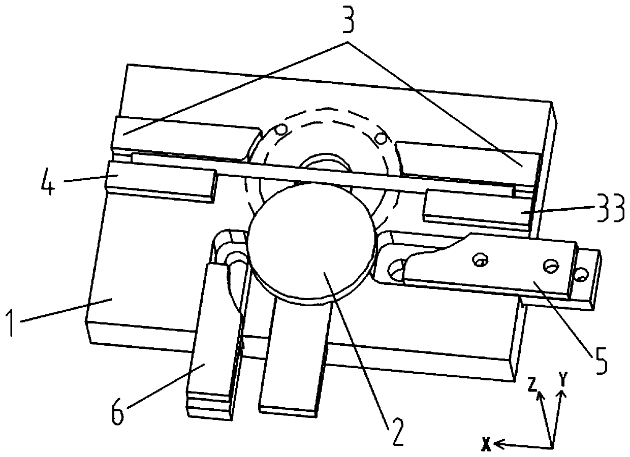
[0049] A multi-step continuous bending device for arc-shaped members in this embodiment, such as figure 1 and figure 2 As shown, it includes a base 1, on which a circular die assembly 2 is slidably arranged in the Y direction, and half rings are arranged on both sides of the circular die assembly 2 along the X direction on the base 1 Shaping assembly 3, the side of the half-ring shaping assembly 3 close to the circular die assembly 2 is provided with a starting positioning block 4 along the X direction, and the half-ring shaping assembly 3 and the starting positioning block 4 are arranged along the X direction. A channel is provided in the direction for components to pass through; the other side of the circular die assembly 2 is provided with a three-quarter ring die assembly 5 sliding along the X direction.

[0050] The base 1 is fixed on the working surface by bolts, and the top of the base 1 is provided with a circular die assembly 2, a half-ring shaping assembly 3, a thr...

Embodiment 2

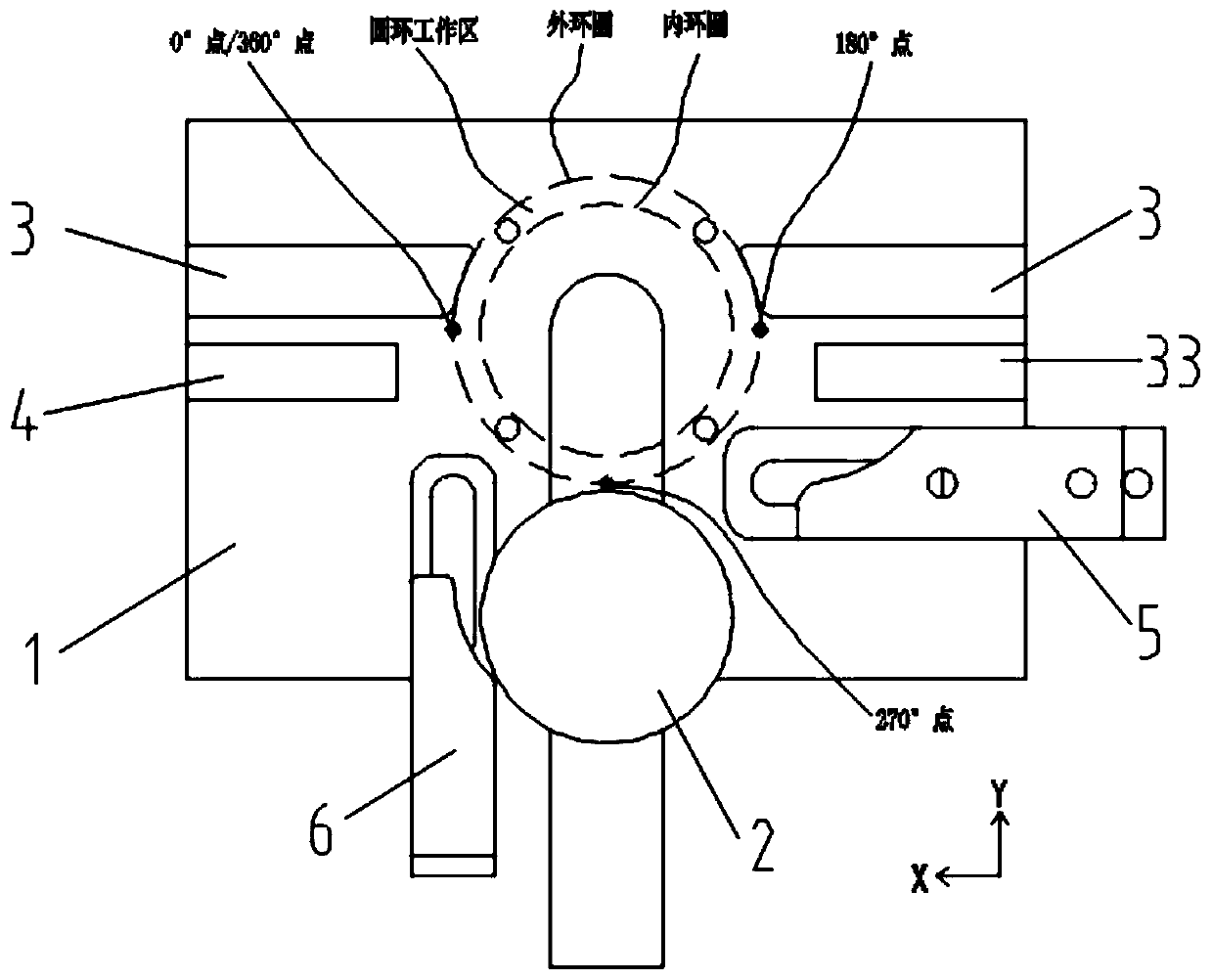
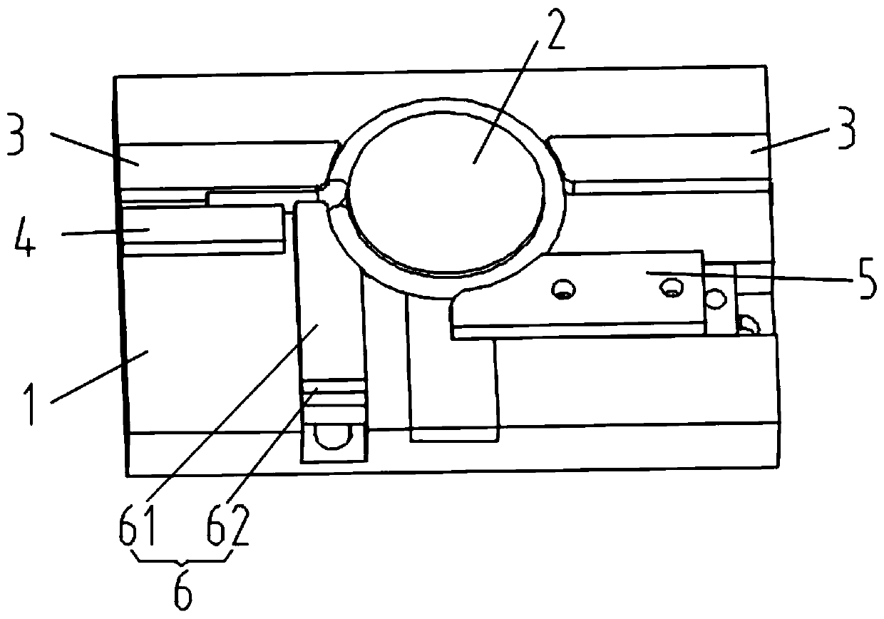
[0059] This embodiment is further optimized on the basis of embodiment 1, such as image 3 , Figure 4 , Figure 16 As shown, one side of the circular die assembly 2 is slidably provided with a full-ring die assembly 6 along the Y direction; the full-ring die assembly 6 includes a full-ring die 61 and a full-ring traction block 62 , the whole-ring traction block 62 is slidably arranged on the base 1 along the Y direction, and the top of the whole-ring traction block 62 is equipped with a whole-ring die 61 and drives the whole-ring die 61 to move along the Y direction. One end of the die 61 close to the circular die assembly 2 is provided with a die arc corresponding to the bending outer contour of the component.

[0060] On the base 1 corresponding to the 360° point of the circular working area, there is a first chute with an opening along the Y direction, and a full-ring traction block 62 is slidably arranged in the first chute, and the top of the entire-ring traction block...

Embodiment 3

[0072] This embodiment is further optimized on the basis of above-mentioned embodiment 1 or 2, such as Figure 5-Figure 7 and Figure 14 As shown, the semi-ring shaping assembly 3 includes a first shaping block 31 and a second shaping block 32, and the first shaping block 31 is provided on both sides of the circular die assembly 2 along the X direction. and the second starting-end shaping block 32; the first starting-ending shaping block 31 is arranged parallel to the starting-end positioning block 4, and there is provided along the X direction between the first starting-end shaping block 31 and the starting-end positioning block 4 for members to pass through channel; the ends of the first starting-end shaping block 31 and the second starting-end shaping block 32 close to the circular die assembly 2 are provided with a die arc corresponding to the outer contour of the member.

[0073] The first shaping block 31 and the second shaping block 32 are respectively arranged at the ...


PUM


Abstract

The invention discloses a multi-step continuous bending device of arc-shaped components. The multi-step continuous bending device comprises a base. A round die pressing assembly is slidingly arrangedon the base in the Y direction, semi-ring setting assemblies are arranged on the portions, on the two sides of the round die pressing assembly, of the base in the X direction correspondingly, startingend positioning blocks are arranged on the sides, close to the round die pressing assembly, of the semi-ring positioning assemblies in the X direction, and a passageway allowing the components to penetrate is formed between the semi-ring setting assemblies and the starting end positioning blocks in the X direction. A three-fourth-ring die pressing assembly is slidingly arranged on the other sideof the round die pressing assembly in the X direction. The multi-step continuous bending device has the beneficial effects that the component bending procedures are simple and convenient to implement,the device is suitable for forming the components of different specifications, and the bending modules are simple in structure and compatible with multi-shape forming of the components.

Description

technical field [0001] The invention belongs to the technical field of component forming, in particular to a multi-step continuous bending device for arc-shaped components. Background technique [0002] With the continuous mature application of plastic processing technology, bars, pipes, square steel and profiles of various cross-sectional shapes (such as T, L, ∏, □) are widely used in production and processing. The shapes of parts are also different, but the most basic There are two cases of straight lines and arcs. Through the combination of different numbers of straight lines and arcs, various arc components can be formed. These components are in great demand in daily life and industrial production. The most common arc components are shown in figure 1 Among them, the half ring, the whole ring, the ring and the cane are the most typical representatives. [0003] These components are generally formed by bending, and each component requires one or more sets of special dies,...

Claims


Application Information

Patent Timeline
Patent Type & Authority Applications(China)
IPC IPC(8): B21D31/00B21D43/00
CPCB21D31/005B21D43/003
Inventor 李光俊黄丹
Owner CHENGDU AIRCRAFT INDUSTRY GROUP
Why Eureka
Try Eureka