
Batch manufacturing device for gears

A manufacturing device and batch technology, applied in the field of manufacturing devices, can solve the problems of low working efficiency of gears, consuming a lot of time and manpower, disadvantageous for mass production of gears, etc., and achieve the effects of simple and convenient operation and high working efficiency.

Active Publication Date: 2022-04-08
南京劲拓机械有限公司
View PDF8 Cites 0 Cited by
  • Summary
  • Abstract
  • Description
  • Claims
  • Application Information

AI Technical Summary

Problems solved by technology

[0004] In order to overcome the disadvantages of low work efficiency, time-consuming and labor-intensive work, which is not conducive to the mass production of gears, the purpose of the present invention is to provide a batch production of gears that does not need to consume more time and manpower and has high work efficiency. manufacturing device

Method used


Image

  • Batch manufacturing device for gears
  • Batch manufacturing device for gears
  • Batch manufacturing device for gears

Examples


Embodiment 1

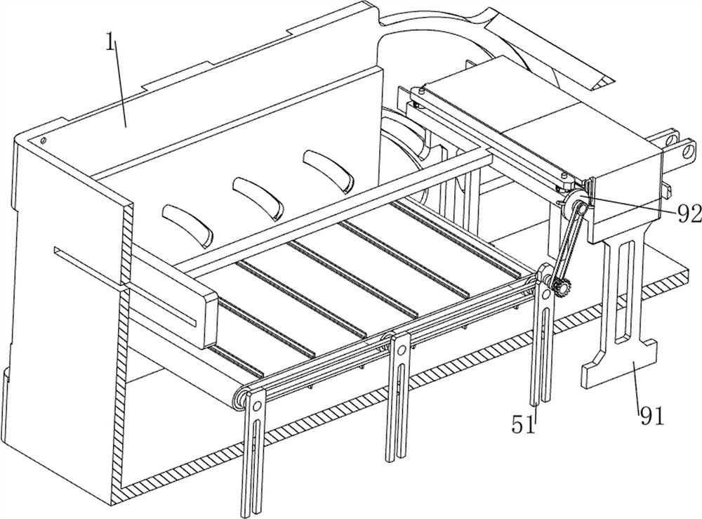
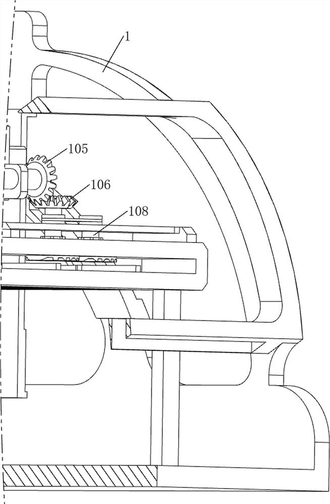
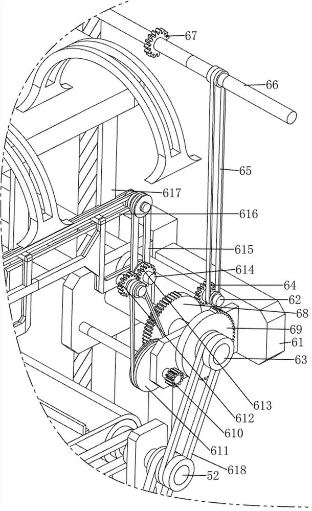
[0035] A batch manufacturing device for gears, such as Figure 1-11 As shown, it includes a protective frame 1, an adapter frame 2, a screw rod 3, a stamping die 4, a transmission mechanism 5, a feeding mechanism 6, an intermittent pressing auxiliary mechanism 7, and a fixing mechanism 8. There is a feeding port on the right side of the protective frame 1. , the upper side of the protective frame 1 is connected with an adapter frame 2, and the front and rear sides of the adapter frame 2 are evenly arranged in a sliding manner connected with four screw rods 3, and the lower side of the screw rod 3 is provided with a stamping die 4, and the protective frame 1 is provided with a transmission mechanism 5, a feeding mechanism 6 is provided on the protective frame 1, an intermittent downward pressure auxiliary mechanism 7 is provided between the screw rod 3 and the feeding mechanism 6, and a fixing mechanism 8 is provided on the feeding mechanism 6.

[0036]When the gears need to be...

Embodiment 2

[0043] On the basis of Example 1, such as figure 2 , Figure 12 , Figure 13 , Figure 14 and Figure 15 As shown, a cutting mechanism 9 is also included, and the cutting mechanism 9 includes a support seat 91, a protrusion 92, a sixth gear 93, a seventh transmission assembly 94 and a cutter 95, and the inner left side of the protective frame 1 is connected with a support seat 91 The rear side of the upper right part of the support seat 91 is rotatably connected with a bump 92, the upper side of the first support frame 51 on the left rear side is rotatably connected with a sixth gear 93, and the sixth gear 93 and the bump 92 are connected with a first Seventh transmission assembly 94, the seventh transmission assembly 94 is made up of two pulleys and a flat belt, wherein one pulley is installed on the sixth gear 93, and the other pulley is installed on the rear side of the bump 92, and the flat belt is wound between the two pulleys , The right part of the support base 91 ...


PUM


Abstract

The invention relates to a manufacturing device, in particular to a batch manufacturing device for gears. The invention aims to provide the batch manufacturing device for the gears, which does not need to consume more time and labor and is high in working efficiency. A batch manufacturing device for gears comprises a protection frame, a connecting frame, lead screws, stamping dies, a conveying mechanism, a feeding mechanism and the like, the connecting frame is connected to the protection frame, the two sides of the connecting frame are each slidably connected with at least two lead screws which are evenly arranged in the left-right direction, and one side of each lead screw is provided with the corresponding stamping die; a conveying mechanism capable of conveying gears is arranged on the protection frame, and a feeding mechanism capable of conveying materials is arranged on the protection frame. A worker can press the gear through a control motor, the manufactured gear and residual materials are automatically moved and conveyed to the left side, operation is easy and convenient, and the working efficiency is high.

Description

technical field [0001] The invention relates to a manufacturing device, in particular to a gear batch manufacturing device. Background technique [0002] In mechanical equipment, gears are often used, so the production of gears is essential, but the production of gears is generally more troublesome. It is necessary to make a blank of appropriate size first, and then draw a tooth pattern on the blank, and then use a cutting tool according to The tooth pattern is proofed and punched, and finally tools such as files are used for grinding and forming. Therefore, the normal production of gears is inefficient and requires a lot of time and manpower, which is not conducive to mass production of gears. [0003] Therefore need to design a kind of batch manufacturing device that does not need to consume more time and manpower, the gear of work efficiency is high. Contents of the invention [0004] In order to overcome the disadvantages of low work efficiency, time-consuming and lab...

Claims


Application Information

Patent Timeline
Patent Type & Authority Applications(China)
IPC IPC(8): B23P23/04B23P23/00
CPCY02P70/10
Inventor 邓敏丽
Owner 南京劲拓机械有限公司
Learn More