Ejector pin exhausting structure

A technology of thimble and exhaust groove, which is applied in the field of molds, can solve the problems of time-consuming and labor-intensive thimble processing, melt blockage and other problems, and achieve the effect of simple processing method

Inactive Publication Date: 2020-02-21
KUNSHAN HANDING PRECISION METAL CO LTD
View PDF9 Cites 0 Cited by
  • Summary
  • Abstract
  • Description
  • Claims
  • Application Information

AI Technical Summary

Problems solved by technology

After analysis, it has the following defects: First, the exhaust strip hole is set on the upper end surface of the thimble, and the upper end surface of the thimble is often in direct contact with the casting, which will inevitably lead to melt blockage over time; secondly, this processing method needs to be done on the thimble Multi-processing, and a product often needs to be set up with multiple thimbles for ejection, so processing each thimble is time-consuming and laborious

Method used


Image

  • Ejector pin exhausting structure
  • Ejector pin exhausting structure

Examples


Embodiment Construction

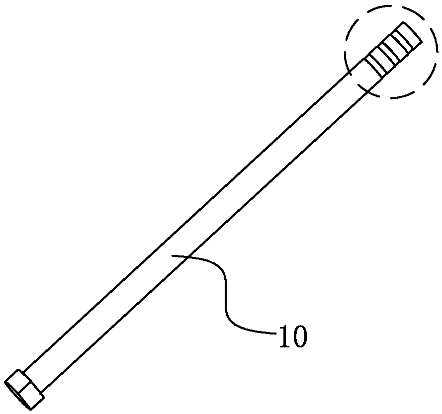
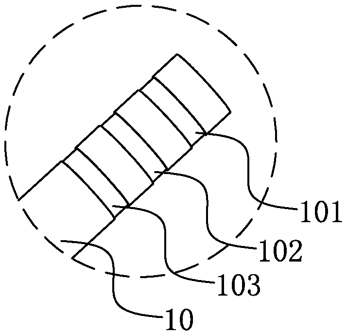
[0018] see figure 1 and figure 2 shown, where figure 1 It is a structural schematic diagram of the thimble exhaust structure of the present invention, figure 2 It is a partially enlarged schematic diagram of the thimble exhaust structure of the present invention.

[0019] The thimble exhaust structure of the present invention includes:

[0020] The thimble body 10 is provided with several exhaust grooves at its upper end, each exhaust groove is spaced with the same length, and the depth of all exhaust grooves is equal;

[0021] There is a certain distance between the top of the thimble body 10 and the nearest exhaust groove 101 below, so that the exhaust groove will not be too close to the casting and be blocked by molten soup, and the exhaust effect can be achieved.

[0022] Optionally, the width of the exhaust grooves 102 is 3 mm, and the depth is 0.2 mm; if the exhaust volume is too large during the molding process, the width of the exhaust grooves can be increased. ...


PUM

PropertyMeasurementUnit
widthaaaaaaaaaa
depthaaaaaaaaaa

Abstract

The invention relates to the technical field of dies, in particular to an ejector pin exhausting structure. The ejector pin exhausting structure comprises an ejector pin body, wherein a plurality of exhausting grooves are formed in the upper end of the ejector pin body, and all the exhausting grooves are evenly spaced, and have equal depth; and a certain distance is formed between the top end of the ejector pin body and the most adjacent exhausting groove at the lower part, so that the exhausting grooves can be prevented from being too close to a casting and blocked by molten liquid, and the exhausting effect can be realized. Compared with the prior art, the ejector pin exhausting structure has the advantages as follows: a plurality of exhausting grooves with equal width are formed in thetop end of the ejector pin body and have a certain distance with the top end of the ejector pin body, so that the exhausting grooves can be prevented from being too close to the casting and blocked bythe molten liquid, and the exhausting effect can be realized; and the structure adopts a simple and easy processing method, has a good exhausting effect and is not prone to blocking.

Description

【Technical field】 [0001] The invention relates to the technical field of molds, in particular to a thimble exhaust structure. 【Background technique】 [0002] During the casting process, gas is generated. For the higher position of the casting structure, there is often poor exhaust, so that the melt cannot completely fill the mold cavity, and the bad situation of forming castings with many pores appears. [0003] In view of the above problems, the industry adopts the following methods to solve them. First, process the entry and exit sub-threads on the entry, that is, form an exhaust groove to assist exhaust, but the entry is mostly fixed during the molding process, and the exhaust of the entry line is often blocked, and subsequent processing to remove the entry will increase cost; in addition, not all situations are suitable for processing sub-lines; second, make slag bags inside the casting, that is, transfer the trapped air parts to the slag bags, and then remove them by ...

Claims


Application Information

Patent Timeline
Patent Type & Authority Applications(China)
IPC IPC(8): B22D17/22
CPCB22D17/22
Inventor 李战
Owner KUNSHAN HANDING PRECISION METAL CO LTD
Why Eureka
Try Eureka