Ejector retainner plate free injection mold and product demoulding method thereof

A technology of injection mold and thimble plate, which is applied in the field of injection mold, can solve the problems of high cost, complex structure, large mold size, etc., and achieve the effect of reducing the overall thickness, reducing the cost of use, and avoiding the phenomenon of product sticking

Pending Publication Date: 2020-02-21
SHENZHEN SILVER BASIS TECH
0 Cites 1 Cited by

AI-Extracted Technical Summary

Problems solved by technology

[0005] The purpose of the present invention is to provide an injection mold without ejector plate and its product de...

Method used

Above-mentioned injection mold 100 without thimble plate, fixed template 11 one side is fixed with the first air-collecting block joint 12 that is communicated with air source device, and fixed template 11 has the first air flow channel 111, is provided with in the first air flow channel 111 There is a first air cap part 13, the first gas cap part 13 includes a first piston member 131 used to push the product and guide the air outlet to the injection cavity when the mold is opened, and the side of the movable template 21 is fixed with a gas source The second air-collecting block joint 22 connected with the device, the movable template 21 has a second air flow channel 211, and the second air-cap component 23 is arranged in the second air-flow channel 211. Push the product and guide the second piston member 231 of the air outlet and the injection cavity, so that the thimble, thimble plate, reset lever and middle drag are omitted, and the largest thimble panel and thimble bottom p...

Abstract

The invention relates to the technical field of injection molds and provides an ejector retainner plate free injection mold and a product demoulding method thereof. The ejector retainner plate free injection mold comprises a fixed mold part and a movable mold part; the fixed mold part comprises a fixed mold plate and a first air collection block joint; the fixed mold plate is provided with a firstair passageway; the movable mold part comprises a movable mold plate and a second air collection block joint; the movable mold plate is provided with a second air passageway; a first air ejection component is arranged in the air outlet of the first air passageway and comprises a first piston component, and the first piston component is used for pushing a product during the mold opening process and enabling the air outlet and an injection molding cavity to communicate; and a second air ejection component is arranged in the air outlet of the second air passageway and comprises a second piston component, and the second piston component is used for pushing the product during the mold opening process and enabling the air outlet and the injection molding cavity to communicate. Compared with theprior art, the ejector retainner plate free injection mold eliminates an ejector pin, the ejector retainer plate, a resetting rod and a middle dragging piece, so that the overall thickness of the mold is reduced, and the using cost of the mold is lowered.

Technology Topic

Image

  • Ejector retainner plate free injection mold and product demoulding method thereof
  • Ejector retainner plate free injection mold and product demoulding method thereof
  • Ejector retainner plate free injection mold and product demoulding method thereof

Examples

  • Experimental program(1)

Example Embodiment

[0065] In order to make the technical problems, technical solutions and beneficial effects to be solved by the present invention clearer, the following further describes the present invention in detail with reference to the accompanying drawings and embodiments. It should be understood that the described embodiments are part of the embodiments of the present invention, rather than all of the embodiments. Based on the described embodiments of the present invention, all other embodiments obtained by a person of ordinary skill in the art without creative work shall fall within the protection scope of the present invention.
[0066] In order to enable those skilled in the art to better understand the technical solutions of the present invention, the implementation of the present invention will be described in detail below with reference to specific drawings.
[0067] For the convenience of description, the “upper” and “lower” referred to below are consistent with the upper and lower directions of the drawings themselves, but do not limit the structure of the present invention.
[0068] Unless otherwise defined, the technical or scientific terms used herein shall have the usual meanings understood by those with ordinary skills in the field to which the present invention belongs. The "first", "second" and similar words used in the specification and claims of the patent application of the present invention do not denote any order, quantity or importance, but are only used to distinguish different components. Similarly, similar words such as "one" or "one" do not mean a quantity limit, but mean that there is at least one.
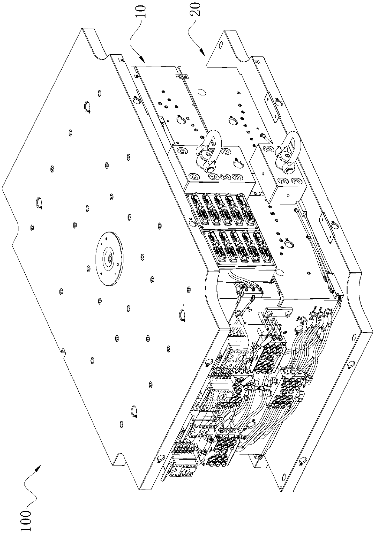
[0069] Such as figure 1 Shown is a preferred embodiment provided by the present invention.
[0070] The ejector-free injection mold 100 provided in this embodiment includes a fixed mold part 10 that can be opened and closed and a movable mold part 20 connected to the fixed mold part 10. The fixed mold part 10 and the movable mold part 20 An injection cavity (not shown) is formed between them, and the fixed mold part 10 includes a fixed template 11 and a first gas gathering block connector 12 fixed on one side of the fixed template 11 and used to communicate with an air source device (not shown); The template 11 has a plurality of first air passages 111, and two ends of each first air passage 111 respectively form an air inlet communicating with the first air collecting block joint 12 and an air outlet communicating with the injection cavity; the movable mold part 20 includes a movable mold. The template 21 and the second air collecting block connector 22 fixed on one side of the movable template 21 and used for communicating with the air source device; the movable template 21 has a plurality of second air passages 211, and two ends of each second air passage 211 are respectively formed The air inlet communicating with the second air collecting block connector 22 and the air outlet communicating with the injection cavity; the air outlet of each first air flow channel 111 is provided with a first air top member 13 that closes the air outlet, and the first air top The part 13 includes a first piston member 131 that is used to push the product (not shown) and communicate with the air outlet when the mold is opened; the air outlet of each second air channel 211 is provided with a closed air outlet The second air cap component 23 includes a second piston component 231 that is used to push the product and communicate with the air outlet when the mold is opened.
[0071] In the above-mentioned injection mold 100 without ejector plate, the fixed plate 11 is fixed with a first air collecting block connector 12 connected to the air source device on one side, the fixed plate 11 has a first air passage 111, and the first air passage 111 is provided with a first The air cap part 13 includes a first piston member 131 connected to the injection cavity for pushing the product and conducting the air outlet when the mold is opened. One side of the movable template 21 is fixed with the air source device The second air-gathering block connector 22, the movable template 21 has a second air flow channel 211, and a second air cap component 23 is provided in the second air flow channel 211. The second air cap component 23 includes a product for pushing and pushing the product when the mold is opened. The second piston member 231 that communicates with the air outlet and the injection cavity, thus eliminating the thimble, thimble plate, reset rod and middle drag, as the largest thimble panel and thimble bottom plate are omitted, thus reducing the overall mold Thickness reduces the use cost of the mold.
[0072] See figure 1 , The ejector-less injection mold 100 of this embodiment includes a fixed mold part 10 (also called a front mold, a master mold, which is a unified technical term, hereinafter collectively referred to as a fixed mold part) and a movable mold part 20 connected to the fixed mold part 10 ( Also called rear mold and male mold, which are unified technical terms, collectively referred to as the movable mold part below), the fixed mold part 10 and the movable mold part 20 can open and close the mold, and an injection cavity is formed between the two when the mold is closed. In this embodiment, the fixed mold part 10 is composed of a panel 14, a backing plate 15 and a fixed mold plate 11 connected sequentially from top to bottom, and the movable mold part 20 is composed of a movable mold plate 21 and a bottom plate 24 sequentially connected from top to bottom. It can be seen that, compared to the mold using the ejector plate as the ejector structure, the ejector plateless injection mold 100 of this embodiment not only has the function of ejecting the product, but also can realize the demoulding of the product, and the ejector plate is omitted. , The structure is more compact and the volume is smaller.
[0073] In another embodiment, the fixed mold portion 10 is composed of a panel 14 and a fixed mold 11 that are connected to each other. The thickness of the fixed mold 11 is greater than that of the fixed mold 11 of the present embodiment, or the thickness of the panel 14 is greater than that of the present embodiment. The thickness of the panel 14 is large.
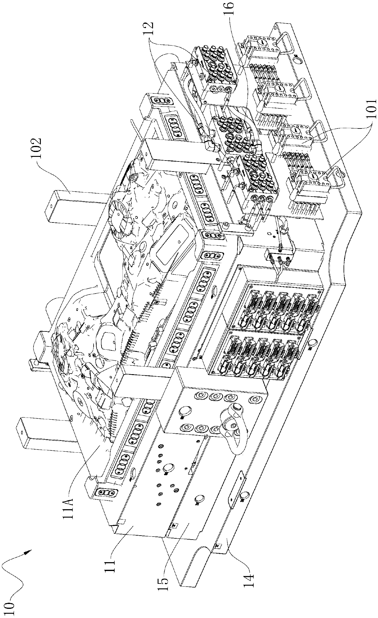
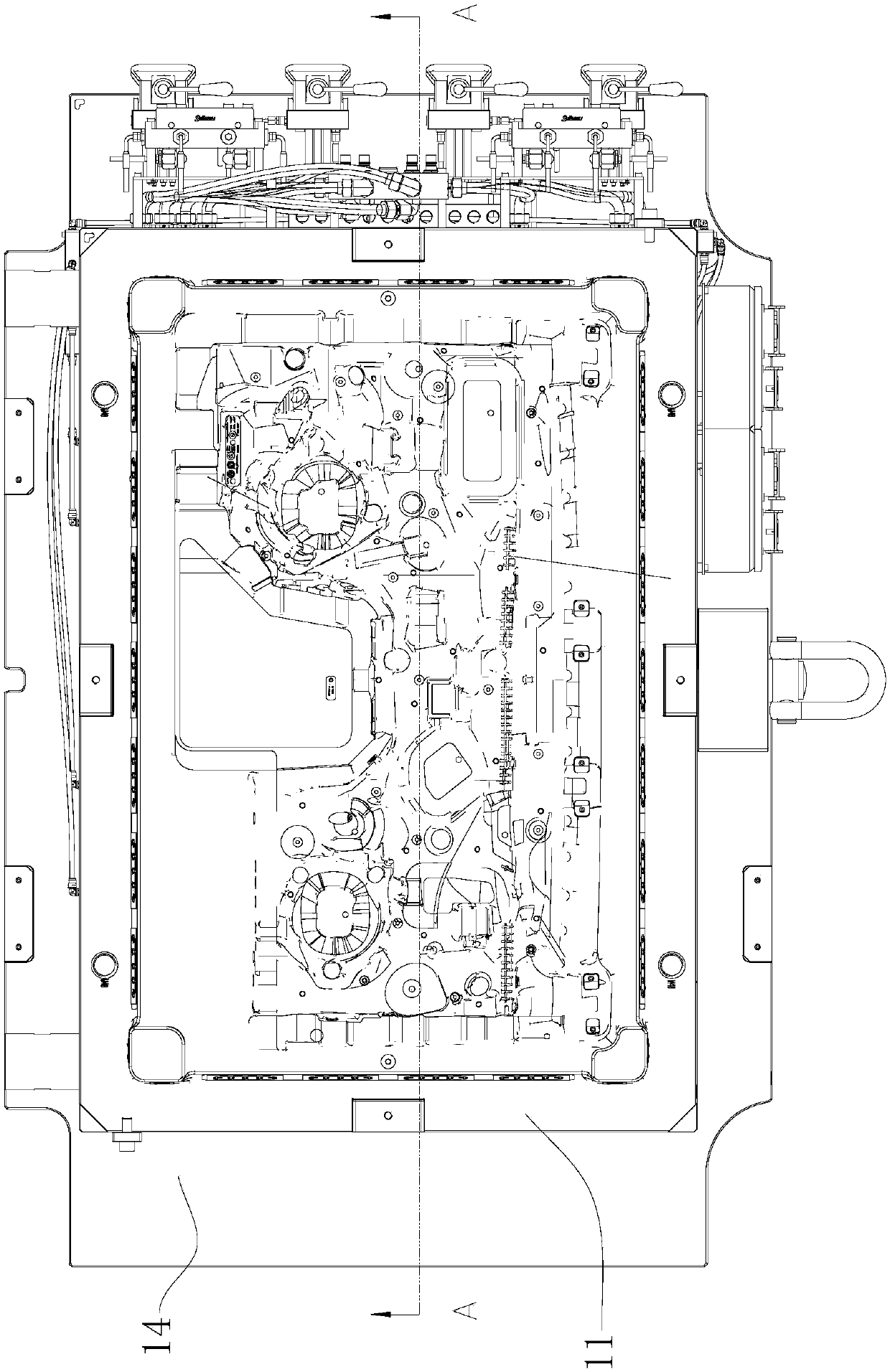
[0074] See Figure 2 to 4 , One side of the fixed template 11 is fixed with a first air-gathering block connector 12 for communicating with the air source device; the fixed template 11 has a plurality of first air channels 111, and both ends of each first air channel 111 are formed with The air inlet communicated with the first air collecting block connector 12 and the air outlet communicated with the injection cavity. In this embodiment, the fixed template 11 has a core member 11a. One end of the first air flow channel 111 extends to the surface of the core member 11a to form an air outlet, and the other end extends to the side wall of the fixed template 11 to form an air inlet. The first air-gathering block connector 12 has a main flow joint and a plurality of branch joints, the main flow joint is connected to the air source device, and each branch joint is connected to each corresponding air inlet, that is, when the air source device is connected When the first gas gathering block connector 12 passes gas, the gas can be blown out from the air outlet of the first gas flow channel 111.
[0075] See Figure 4 to 6 The air outlet of each first air flow channel 111 is provided with a first air cap member 13 that closes the air outlet, and the first air cap member 13 includes an injection molding machine for pushing the product and conducting the air outlet when the mold is opened. The first piston member 131 of the cavity. In this embodiment, the number of the first air-top components 13 provided on the fixed template 11 is but not limited to twenty-eight, preferably at the glue position of the deep cavity, the position of the wrapping core member 11a, and the bottom of the large slope , The first gas top part 13 is arranged on the large plane. The first air top component 13 includes a first mounting sleeve 132 and a first piston member 131. The first mounting sleeve 132 is fixed on the inner wall of the air outlet of the first air passage 111, and the first piston member 131 is slidably connected to the first mounting A sleeve 132, a first elastic member 133 is arranged between the first mounting sleeve 132 and the first piston member 131, for making the first piston member 131 move after the first piston member 131 moves relative to the first mounting sleeve 132 Reset movement.
[0076] Referring to 5 and 6, specifically, the first mounting sleeve 132 is a cylindrical structure with open ends. It has an inner end 1321, an outer end 1322 close to the surface of the core member 11a, and a through groove 1323 through which the through groove 1323 penetrates. The inner end 1321 and the outer end 1322. The first piston member 131 includes a head portion 1311, a tail portion 1312, and a rod portion 1313 connected between the head portion 1311 and the tail portion 1312. The rod portion 1313 is disposed in the through groove 1323 with a preset gap between them, To allow air to pass through, the head 1311 can open and close the outer end 1322. The first elastic member 133 is but not limited to a spring. The two ends of the spring are connected to the first mounting sleeve 132 and the first piston member 131 respectively. It can be understood that the separation of the product and the fixed template 11 is divided into two stages. The first stage is when the mold is opened, the gas source device sends high-pressure gas, and the gas flows to the top of each first gas through the first gas flow channel 111 The first piston member 131 is pushed up, so that the head 1311 of the first piston member 131 pushes the product away from the fixed template 11; the second stage is after the first piston member 131 moves to the maximum stroke, Since the air outlet of the first air channel 111 is in an open state, the high-pressure gas flows out from the air outlet and continues to push the product, thereby separating the product from the fixed template 11. After the air source device is closed, the elastic force of the first elastic member 133 is used to quickly reset the first piston member 131 and close the air outlet.
[0077] In particular, since the mold of this embodiment is made of a soft rubber product, the product is easy to stick to the film, and the traditional ejector pin and ejector block will cause the product to appear white and deformed. This implementation is adopted The demoulding and separating structure in the example can effectively prevent the product mucosa and avoid the phenomenon of whitening and deformation of the product when it is ejected.
[0078] See Figure 2 to 10 A first water collecting block connector 16 for connecting with a water source device is fixed on one side of the fixed template 11, and the fixed template 11 has a plurality of first water flow passages 112 respectively communicating with the first water collecting block connector 16. In this embodiment, a first groove 141 is formed on the side surface of the panel 14 facing the backing plate 15 and a second groove 151 is formed on the side surface of the backing plate 15 facing the panel 14. The panel 14 and the backing plate 15 are connected to form a first groove 141. An internal space 14a, in which a cooling water plate 161 connected to the first water flow channel 112 is provided for cooling the fixed mold part 10.
[0079] The ejector-less injection mold 100 of this embodiment uses a hot runner system to ensure that the plastics of the runner and gate remain molten by heating components. The entire runner from the nozzle outlet of the injection molding machine to the gate is in a high temperature state, so that The plastic in the runner is kept molten. It is generally not necessary to open the runner to take out the condensate after the machine is shut down, and only need to heat the runner to the required temperature when the machine is turned on.
[0080] Please continue to see Figure 2 to 10 , The fixed mold part 10 also includes a hot runner manifold 17, a valve needle hot nozzle 18 and a valve needle drive device 19. In this embodiment, the hot runner manifold 17 and the valve needle drive device 19 are both set in the internal space 14a , The fixed mold part 10 is provided with a main runner connected to the injection port of the panel 14, and the hot runner manifold 17 has a plurality of runners 171, which are respectively connected with the main runner. Each branch 171 is provided with a valve needle hot nozzle 18, which includes a hot nozzle 181 for injection molding and a valve needle 182 for switching the hot nozzle 181. One end of the valve needle 182 extends into In the hot nozzle 181, the other end is connected to the valve needle driving device 19, and the valve needle driving device 19 controls movement.
[0081] Specifically, the valve needle driving device 19 is an oil cylinder, and one side of the fixed template 11 is fixed with an oil collecting block connector 101 connected to the oil cylinder. The oil collecting block connector 101 can be connected with the hydraulic device of the injection machine to form a hydraulic circuit. The driving device 19 realizes the opening and closing movement of the valve needle 182 and controls the injection of molten plastic into the injection cavity. In this way, since the valve gate is closed by the mechanical action of the valve needle 182, it is not limited by the cooling time of the plastic at the gate. In this way, the production and molding cycle of plastic parts can be greatly shortened and the productivity can be improved.
[0082] In another embodiment, the valve needle driving device 19 may also be a cylinder, which is controlled by compressed gas.
[0083] See Figure 11 to 14 , One side of the movable template 21 is fixed with a second gas-collecting block connector 22 for communicating with the air source device. The movable template 21 has a plurality of second air passages 211, and both ends of each second air passage 211 are respectively formed with The air inlet connected to the two gas-collecting block joint 22 and the air outlet connected to the injection cavity. In this embodiment, the movable template 21 has a cavity member 21a. One end of the second air channel 211 extends to the surface of the cavity member 21a to form an air outlet, and the other end extends to the side wall of the movable template 21 to form an air inlet. The second air-gathering block connector 22 has a main flow joint and a plurality of branch joints, the main flow joint is connected with the air source device, and each branch joint is connected with each corresponding air inlet, that is, when the air source device is connected When the second gas gathering block connector 22 passes gas, the gas can be blown out from the air outlet of the second gas flow channel 211.
[0084] The air outlet of each second air channel 211 is provided with a second air cap member 23 that closes the air outlet, and the second air cap member 23 includes an injection cavity for pushing the product and conducting the air outlet when the mold is opened. The second piston member 231. In this embodiment, the structure of the second air top member 23 is the same as that of the first air top member 13, and the number of the second air top members 23 provided on the movable template 21 is but not limited to twenty-eight, preferably At the glue position of the deep cavity, the position corresponding to the position of the wrapping core member 11a, the bottom of the large slope, and the position of the large plane is provided with a second air top component 23. The second air top component 23 includes a second mounting sleeve 232 and a second piston member 231, the second mounting sleeve 232 is fixed on the inner wall of the air outlet of the second air passage 211, and the second piston member 231 is slidably connected to the second mounting A second elastic member 233 is provided between the sleeve 232, the second mounting sleeve 232 and the second piston member 231. The second elastic member 233 is a spring, and two ends of the spring are respectively connected to the second mounting sleeve 232 and the second piston member 231. Here, the structure of the second air top component 23 will not be repeated. It is worth mentioning that the separation of the product and the movable mold plate 21 is also divided into two stages. The first stage is that after the product is separated from the fixed mold plate 11, the gas source device sends high-pressure gas, and the gas flows through the second gas flow channel 211 To each of the second air top parts 23, the second piston member 231 lifts up and partially pushes the product away from the moving template 21; the second stage is after the second piston member 231 moves to the maximum stroke, due to the second air flow passage 211 The air outlet is in an open state, and the high-pressure gas flows out from the air outlet and continues to push the product, so that the product is separated from the movable template 21, and then the product is taken out by the robot. The whole movement is smooth and the ejection effect is very good. After the air source device is closed, the elastic force of the second elastic member 233 is used to quickly reset the second piston member 231 and close the air outlet.
[0085] See Figure 11 to 13 , One side of the movable template 21 is fixedly fixed with a second water collection block connector 25 for connecting with the water source device, and the movable template 21 has a plurality of second water flow passages 212 respectively communicating with the second water collection block connector 25 for matching The movable mold part 20 is cooled down in temperature.
[0086] See Picture 11 As a further optimization, a balance block 26 is provided between the fixed template 11 and the movable template 21. In this embodiment, the balance block 26 is provided on the parting surface of the movable template 21 to balance the clamping pressure of the mold parting surface when the mold is closed.
[0087] See Figure 1 to 13 As a further optimization, a guide post 102 is provided on the fixed template 11, and a guide groove 27 for the guide post 102 to slide in and out is formed on the movable template 21. In this embodiment, the cross section of the guide post 102 is, but not limited to, a rectangular shape, and the guide post 102 is guided by the cooperation of the guide groove 27 to improve the stability of mold opening and closing.
[0088] The product demolding method provided in this embodiment uses the above-mentioned ejector-less injection mold 100, which includes the following steps:
[0089] When the mold is opened, air is introduced into the first air flow channel 111, so that the first piston member 131 pushes the product and at the same time opens the air outlet of the first air flow channel 111;
[0090] After the first piston member 131 moves by a preset stroke, the product is separated from the fixed template 11 by using the gas flowing out of the air outlet of the first air channel 111;
[0091] Gas is then introduced into the second air passage 211, so that the second piston member 231 pushes the product, and at the same time opens the air outlet of the second air passage 211;
[0092] After the second piston member 231 moves by a preset stroke, the gas flowing out of the air outlet of the second air channel 211 separates the product from the movable template 21.
[0093] The above product demolding method adopts the above-mentioned non-thimble plate injection mold 100, which can effectively demold the product and avoid the occurrence of product mucosal phenomenon.
[0094] The above descriptions are only preferred embodiments of the present invention, and are not intended to limit the present invention. Any modification, equivalent replacement or improvement made within the spirit and principle of the present invention shall be included in the protection of the present invention. Within range.

PUM

no PUM

Description & Claims & Application Information

We can also present the details of the Description, Claims and Application information to help users get a comprehensive understanding of the technical details of the patent, such as background art, summary of invention, brief description of drawings, description of embodiments, and other original content. On the other hand, users can also determine the specific scope of protection of the technology through the list of claims; as well as understand the changes in the life cycle of the technology with the presentation of the patent timeline. Login to view more.

Similar technology patents

Method and device for displaying search results

InactiveCN105630908AReduce use costIncrease the amount of information on a single screenWeb data indexingSpecial data processing applicationsResult typeSearch engine results page
Owner:BEIJING QIHOO TECH CO LTD +1

Server chassis

Owner:GIGA BYTE TECH CO LTD

Inference engine-based logistics billing system and logistics billing method

InactiveCN106372963AAchieve the effect of real-time cost calculationReduce use costLogisticsMarketingBilling systemLogistics management
Owner:石化盈科信息技术有限责任公司

Classification and recommendation of technical efficacy words

  • Reduce use cost
  • Reduce overall thickness

Smart home system based on internet of things cloud computing

Owner:中国联合网络通信有限公司物联网研究院

Fabricated invisible-beam floor plate

InactiveCN108385885AOvercoming construction techniquesReduce overall thicknessFloorsFloor plateRebar
Owner:BEIJING UNIV OF TECH

Novel offset printing and hot stamping technique

InactiveCN103921542AReduce overall thicknessAvoid quality problemsBronze printingRotary lithographic machinesHot stampingUV curing
Owner:广西真龙彩印包装有限公司
Why Eureka
Try Eureka