
Soil sampling device for geological exploration

A soil-taking device and geological survey technology, which is applied in the field of foundation soil survey, construction, infrastructure engineering, etc., can solve the problems of soil sample falling off, soil-taking failure, and low-efficiency soil-taking, so as to increase the success rate and avoid The effect of displacement

Active Publication Date: 2020-02-21
CHONGQING VOCATIONAL INST OF ENG
View PDF7 Cites 5 Cited by
  • Summary
  • Abstract
  • Description
  • Claims
  • Application Information

AI Technical Summary

Problems solved by technology

[0002] When the existing earth-extractor for geological survey extracts the sample upwards, due to the large cohesive force between the soil sample and the subsoil, only the friction force between the soil sample and the inner wall of the soil-borrowing cylinder is used to make the test soil sample and the subsoil Separation often leads to the failure of soil extraction. It takes multiple soil extractions to succeed. The efficiency of soil extraction is low, and when the soil is removed from the ground after soil extraction, the soil sample is easy to fall off from the soil extraction cylinder due to the unobstructed structure at the bottom.

Method used


Image

  • Soil sampling device for geological exploration
  • Soil sampling device for geological exploration
  • Soil sampling device for geological exploration

Examples


Embodiment 1

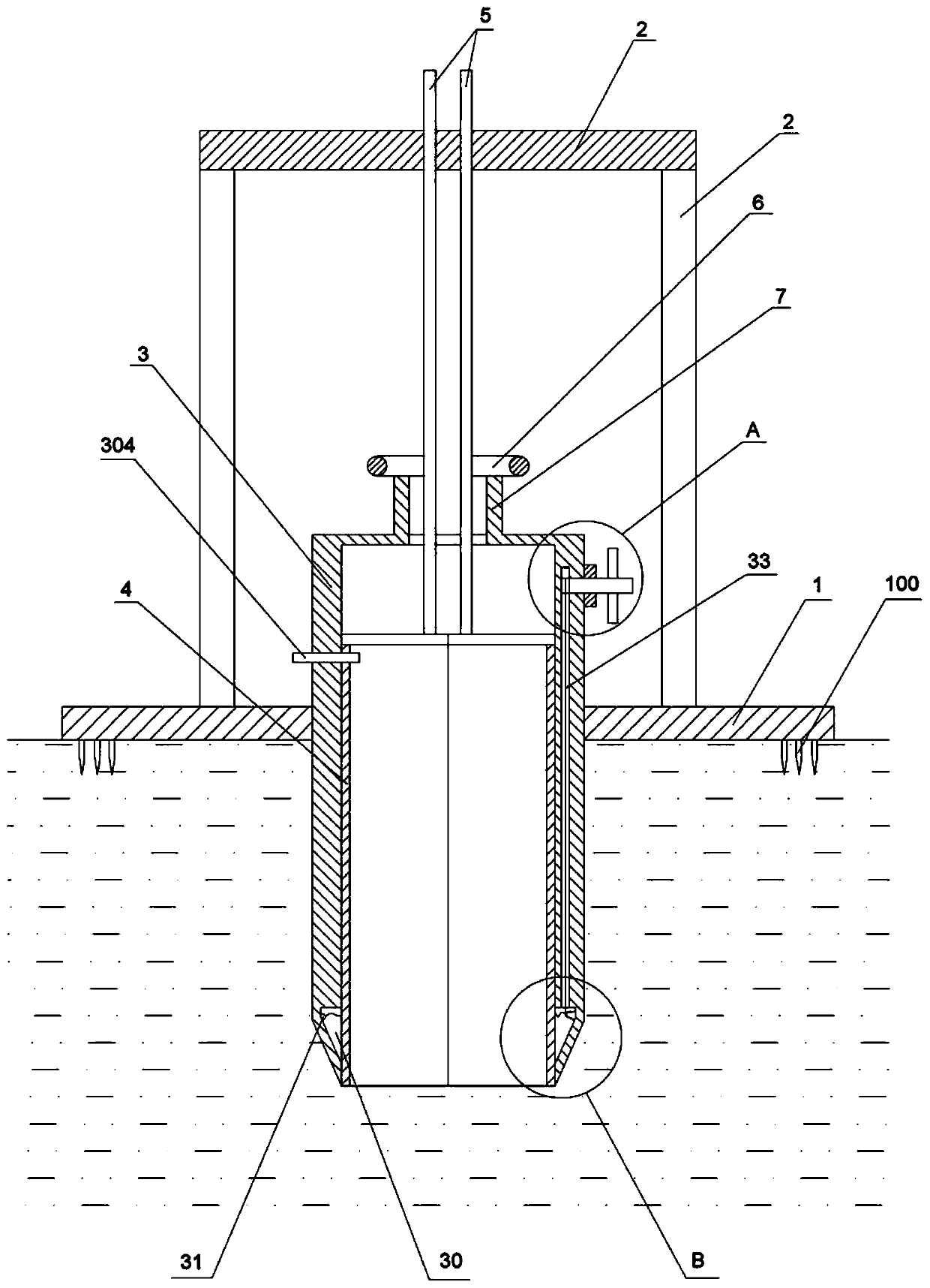
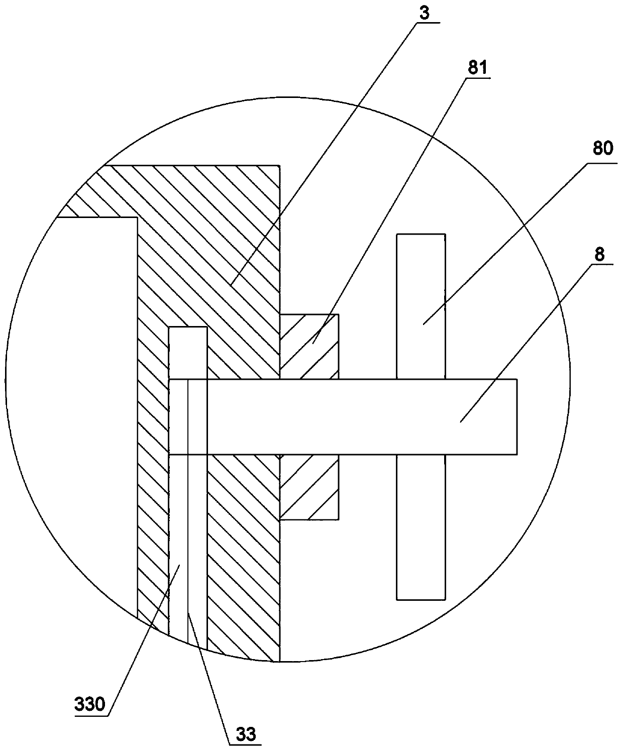
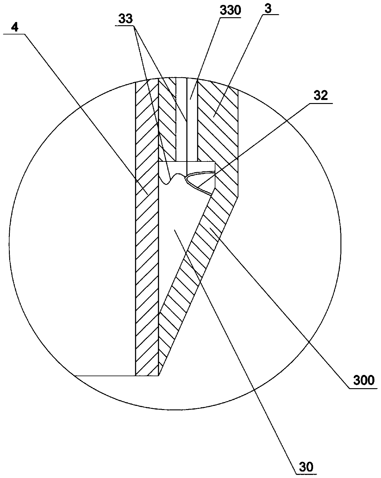
[0028] like figure 1 As shown, a soil-taking device for geological survey in this embodiment includes an inner cylinder 4 and an outer cylinder 3 that are nested in phase, and the tops of the outer cylinder 3 and the inner cylinder 4 are correspondingly provided with through holes, and a through hole is provided in the through hole. The bolt 304 is inserted into the through hole to realize the locking between the outer cylinder 3 and the inner cylinder 4 . There is also a support frame on the outside of the outer cylinder 3. The support frame includes a chassis 1 for fixing on the ground and a frame body 2 fixed on the chassis 1. A round hole is opened on the chassis 1, and the outer cylinder 3 is slidably connected in the round hole. , The bottom of the chassis 1 is also fixed with a claw 100 for inserting into the soil layer. The inner cylinder 4 is spliced ​​by two semi-cylindrical shells, and an anti-rotation rod 5 is integrally formed on the top of the two semi-cylindric...

Embodiment 2

[0035] The difference between this embodiment and Embodiment 1 lies in: combining Figure 4 Shown, the quantity of soil cutting rope 33 is four in the present embodiment. When the four soil cutting ropes 33 rotate, the cutting effect on the bottom of the soil sample in the inner tube 4 is better.


PUM


Abstract

The invention belongs to the field of equipment for geological exploration, and particularly discloses a soil sampling device for the geological exploration. The soil sampling device comprises an inner cylinder and an outer cylinder which are sleeved with each other, wherein the outer cylinder can rotate outside the inner cylinder and can move vertically relative to the inner cylinder, a soil cutting assembly is arranged at the bottom in the outer cylinder and comprises a plurality of soil cutting ropes and a plurality of threading assemblies, the plurality of threading assemblies and the plurality of soil cutting ropes are in one-to-one correspondence, each threading assembly comprises a fixed ring and a threading ring which are fixed at the bottom of the inner wall of the outer cylinder,one end of each soil cutting rope is fixed on the fixed ring, the other end penetrates through the threading ring and extends out of the top of the outer cylinder, and each soil cutting rope is divided into a transverse cutting part and a vertical moving part by the fixed ring and the threading ring of each threading assembly. The bottom of a soil sample in the inner cylinder can be completely cut off through rotation of the soil cutting ropes, adhesion between the soil sample and subsoil is cut off, and when the inner cylinder is lifted upwards for soil sampling, pull force of the subsoil onthe soil sample in the inner cylinder is absent, so that the success rate of soil sampling is greatly increased.

Description

technical field [0001] The invention relates to the field of equipment for geological survey, in particular to a soil-taking device for geological survey. Background technique [0002] When the existing earth-extractor for geological survey extracts the sample upwards, due to the large cohesive force between the soil sample and the subsoil, only the friction force between the soil sample and the inner wall of the soil-borrowing cylinder is used to make the test soil sample and the subsoil Separation often leads to the failure of soil extraction, which requires repeated soil extraction to succeed, and the soil extraction efficiency is low, and when the soil is removed from the ground after the soil is extracted, the soil sample is easy to fall off from the soil extraction cylinder due to the non-blocking structure at the bottom. Contents of the invention [0003] The object of the present invention is to provide a soil-taking device for geological survey, which can increase...

Claims


Application Information

Patent Timeline
Patent Type & Authority Applications(China)
IPC IPC(8): E02D1/04
CPCE02D1/04
Inventor 代秋蕾
Owner CHONGQING VOCATIONAL INST OF ENG
Learn More