Floor drain with low head loss

A low-head, floor-drain technology, applied in waterway systems, water supply devices, drainage structures, etc., can solve problems such as energy loss, affecting water flow velocity, and reducing drainage flow, so as to reduce energy loss, increase water flow velocity, and increase drainage flow. Effect

Pending Publication Date: 2020-02-21
JOMOO KITCHEN & BATHROOM
View PDF0 Cites 3 Cited by
  • Summary
  • Abstract
  • Description
  • Claims
  • Application Information

AI Technical Summary

Problems solved by technology

[0002] There are many corners inside the traditional floor drain. When draining water, the impact of high-speed water flow will cause splashing effect, resulting in energy loss, which will affect the water flow velocity and reduce

Method used


Image

  • Floor drain with low head loss
  • Floor drain with low head loss
  • Floor drain with low head loss

Examples


Example Embodiment

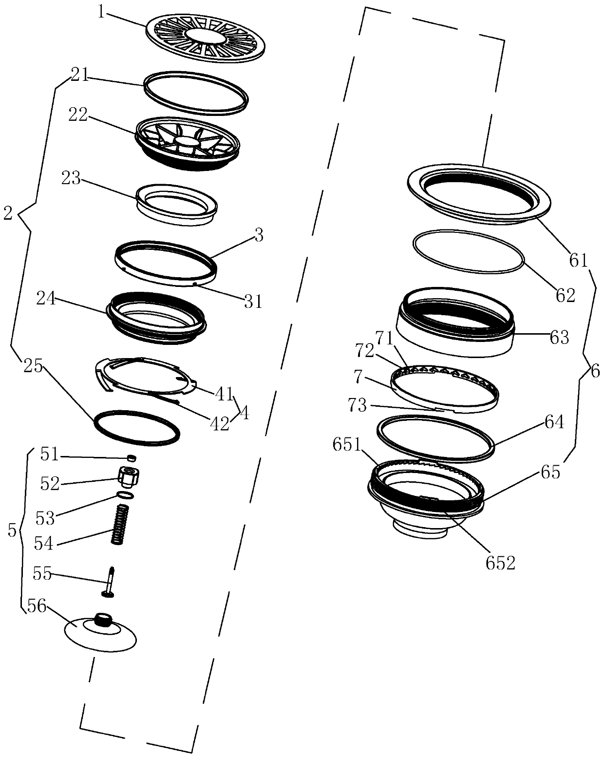
[0047] Examples, see Figure 1-Figure 18 As shown, a floor drain with low head loss of the present invention includes a housing unit 6 and a water inlet unit 2, the water inlet unit 2 is located in the housing unit 6; the inner surface of the water inlet unit 2 is provided with a first guide curved surface 26, The inner surface of the shell unit 6 is provided with a second flow guide curved surface 653. After the fluid enters the water inlet unit 2, it flows against the first flow guide curved surface 26 and the second flow guide curved surface 653 in sequence, and the bottom end of the second flow guide surface 653 forms a The outlet at the bottom of the floor drain. The vertical sections of the first curved flow guide surface 26 and the second curved flow guide surface 653 respectively include the fastest curves to make the fluid flow faster.

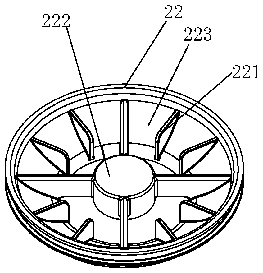
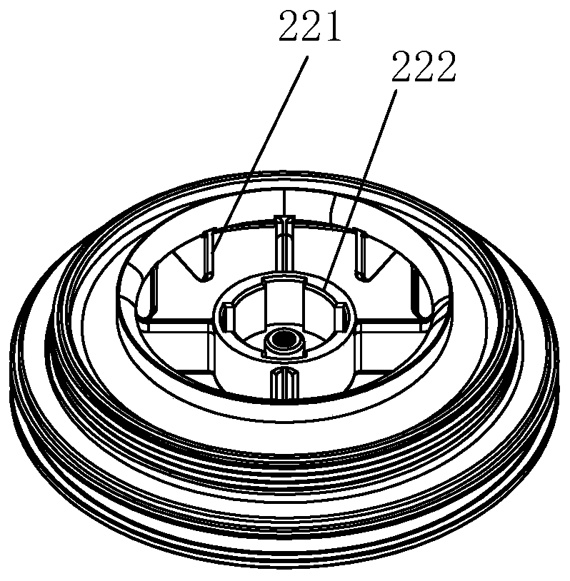
[0048] In this embodiment, the water inlet unit 2 includes a water inlet seat 22, a bracket 24 screwed to the bottom of the water i...


PUM


Abstract

The invention discloses a floor drain with low head loss. The floor drain with low head loss comprises a shell unit and a water inlet unit. The water inlet unit is located in the shell unit. A first flow guiding curved surface is arranged on the inner side face of the water inlet unit. A second flow guiding curved surface is arranged on the inner side face of the shell unit. Fluid enters the waterinlet unit, and then flows against the first flow guiding curved surface and the second flow guiding curved surface, wherein a drain outlet at the bottom of a floor drain is formed in the bottom endof the second flow guiding curved surface. According to the floor drain with low head loss, because the first flow guiding curved surface and the second flow guiding curved surface are arranged, the places, wherein water flows through, in the floor drain are all or almost curved surfaces, the curved surfaces are used for guiding water flow, energy loss in water flow impact is reduced, the water flow can be higher in flowing speed, and then the drainage flow is increased; and in addition, the coanda effect is created when water flows through the first flow guiding curved surface and the secondflow guiding curved surface, so that the interior of the floor drain body and a drain pipe connected with the floor drain body are filled with water, the siphonage appears, and then the drainage flowis further increased.

Description

technical field [0001] The invention relates to a floor drain, in particular to a floor drain with low water head loss. Background technique [0002] There are many corners inside the traditional floor drain. When draining water, the impact of high-speed water flow produces splashing effect, resulting in energy loss, which affects the flow rate of water flow and reduces the drainage flow. For this reason, a floor drain with a curved surface inside has appeared in the prior art. However, this floor drain only has a small section of curved surface on the inner top. cause a large energy loss. Contents of the invention [0003] The object of the present invention is to provide a floor drain with low water head loss aiming at the technical problems existing in the prior art. [0004] The technical solution adopted by the present invention to solve the technical problem is: a floor drain with low water head loss, including a shell unit and a water inlet unit, the water inlet u...

Claims


Application Information

Patent Timeline
IPC IPC(8): E03F5/04E03F5/042
CPCE03F5/0407E03F5/041E03F5/042E03F2005/0417
Inventor 林孝发林孝山梁绍团郑继隆王帆
Owner JOMOO KITCHEN & BATHROOM
Why Eureka
Try Eureka