Tunnel groove forming die trolley

A mold trolley and groove technology, which is used in tunnels, tunnel lining, shaft lining, etc., can solve the problems of inconvenient adjustment of the mold trolley and easy damage to the groove, so as to prevent damage, improve stability, and improve consistency. Effect

Inactive Publication Date: 2020-02-21
安徽豆智智能装备制造有限公司
View PDF0 Cites 2 Cited by
  • Summary
  • Abstract
  • Description
  • Claims
  • Application Information

AI Technical Summary

Problems solved by technology

[0004] The technical problem to be solved by the present invention is to provide a mold trolley that prevents the groove edges from being damaged, and can conveniently adjust the relative height and distance of the groove molds on both sides; The groove is easily damaged and the mold trolley is inconvenient to adjust the height and distance of the mold

Method used


Image

  • Tunnel groove forming die trolley
  • Tunnel groove forming die trolley
  • Tunnel groove forming die trolley

Examples


Embodiment Construction

[0023] In order to make the object, technical solution and advantages of the present invention clearer, the present invention will be further described in detail below in conjunction with specific embodiments and with reference to the accompanying drawings.

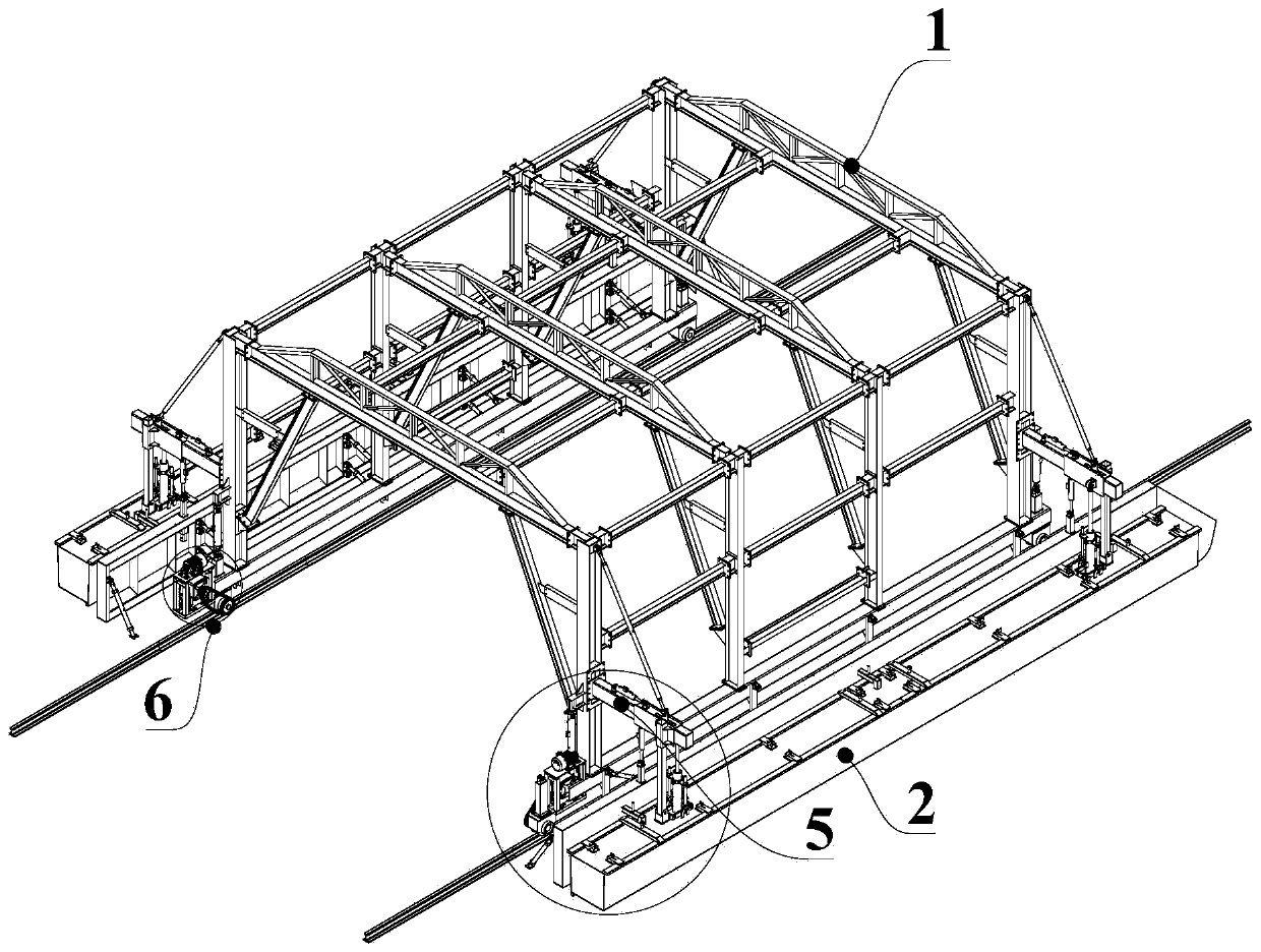
[0024] Such as figure 1 As shown, the present embodiment provides a tunnel groove forming mold trolley, which includes a body 1 spanning both sides of the tunnel. The body 1 is a frame structure with a driving passage (not shown) in the middle. The groove mold 2 and the groove baffle plate 3 between the groove mold 2 and the body 1 are respectively suspended and fixed outwardly, and the vertical height of the groove mold 2 and the groove baffle plate 3 can be independently adjusted respectively, The groove mold 2 and the groove baffle plate 3 on the same side can adjust the relative distance from the body 1 as a whole.

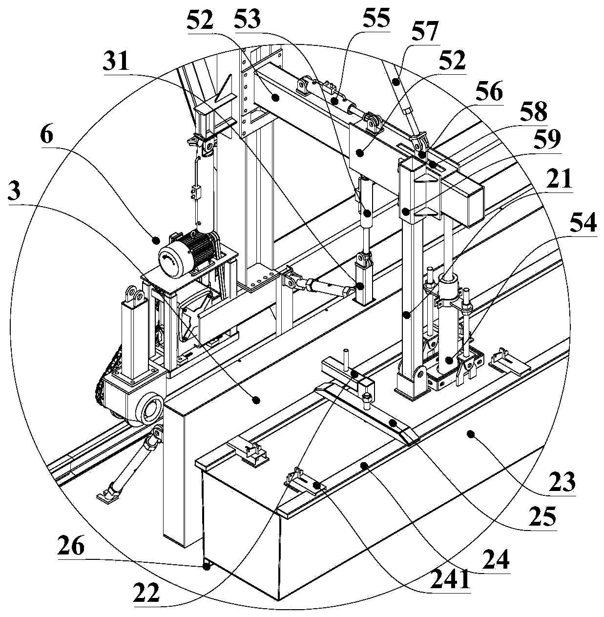
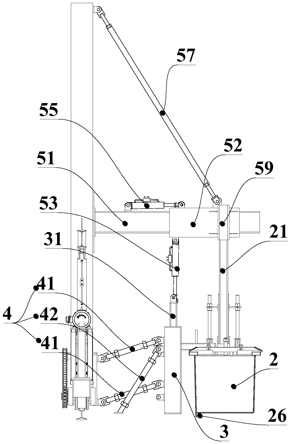
[0025] combine figure 2 and image 3 , the mold 2 includes a mold body 23 for forming the internal...


PUM


Abstract

The invention provides a tunnel groove forming die trolley. The tunnel groove forming die trolley comprises a body stretching across the two sides of a tunnel, wherein groove dies and groove baffles positioned between the groove dies and the body are fixed to the two sides of the body in an outward suspension manner correspondingly; the vertical height of each groove die and the vertical height ofeach groove baffle can be independently adjusted; the relative distance between the groove die and the body and the relative distance between the groove baffle and the body can be integrally adjusted; the groove die and the groove baffle are positioned on the same side; each groove die comprises a die body used for forming the internal structure of a groove and square pipes arranged on the two sides of the upper surface of the die body in the length direction; and the square pipes can move along the upper surface of the body to stretch out of the die body in a suspension manner or contract into the die body. The tunnel groove forming die trolley has the beneficial effects that the height of each groove die and the height of each groove baffle and the distance between the groove die and the center of the tunnel are independently adjusted, the square pipes used for forming cover plate steps contract, and therefore corner angle damage during die releasing is prevented.

Description

technical field [0001] The invention relates to the technical field of tunnel construction equipment, in particular to a tunnel groove forming mold trolley. Background technique [0002] After the construction of the invert layer and the filling layer of the tunnel pavement, it is necessary to construct a water trench cable trench inside the tunnel side wall. In order to facilitate the control of the height and position of the trench on both sides of the tunnel without affecting the normal operation in the tunnel, the existing technology Generally, a mold trolley is used and groove molds are fixed on both sides. However, there are turns and unequal heights in the tunnel. At this time, the positions of the groove molds on both sides need to be adjusted. In the prior art, the mold trolley needs to be moved longitudinally along the tunnel to adjust the position of the groove molds on both sides relative to the center of the tunnel. It is very inconvenient to move the heavy mol...

Claims


Application Information

Patent Timeline
Patent Type & Authority Applications(China)
IPC IPC(8): E21D11/10
CPCE21D11/102E21D11/105
Inventor 陆利
Owner 安徽豆智智能装备制造有限公司
Why Eureka
Try Eureka