
Panel lamp with skylight effect and implementation method thereof

An implementation method and technology for panel lights, which are applied to the components of lighting devices, optical elements used to change the spectral characteristics of emitted light, lighting devices, etc., can solve the problems of no decorative effect and common and single form.

Pending Publication Date: 2020-02-21
HENGDIAN GRP TOSPO LIGHTING
View PDF5 Cites 3 Cited by
  • Summary
  • Abstract
  • Description
  • Claims
  • Application Information

AI Technical Summary

Problems solved by technology

[0003] The existing panel lights have the problem of being too common and single in use, and have no decorative effect

Method used


Image

  • Panel lamp with skylight effect and implementation method thereof
  • Panel lamp with skylight effect and implementation method thereof
  • Panel lamp with skylight effect and implementation method thereof

Examples


Embodiment 1

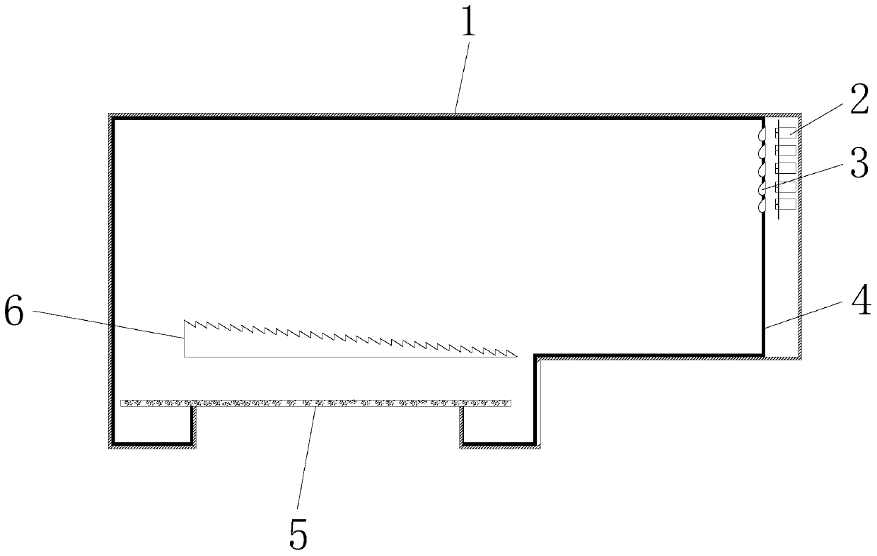
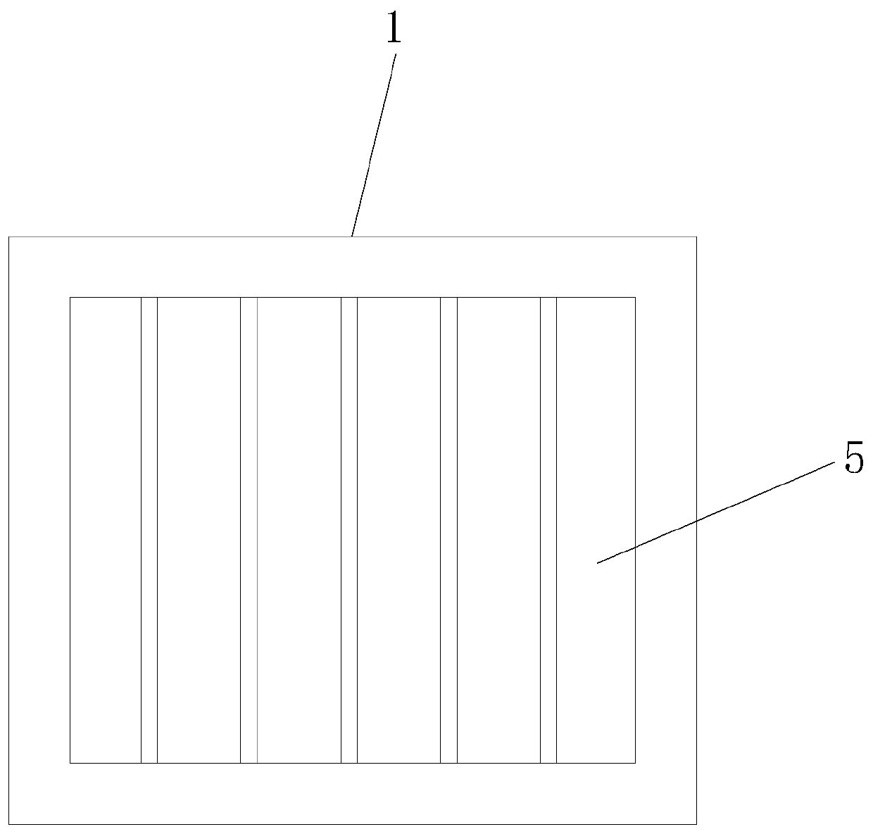
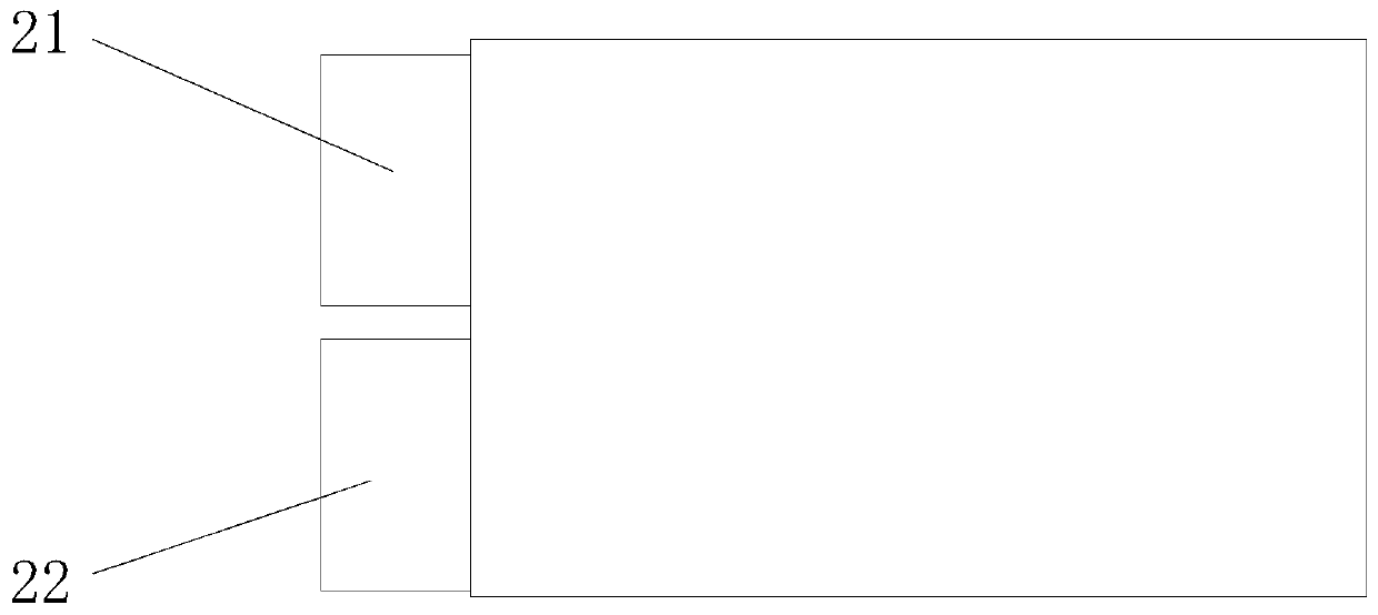
[0032] see Figure 1-3 , the present invention provides the following technical solutions: a panel light showing the effect of a skylight, comprising an outer casing 1, six light-transmitting panels 5 are connected below the outer casing 1, a collimating lens 6 is arranged above the light-transmitting panels 5, and the casing One side of the upper end of the body 1 is connected with five light sources 2, and the five light sources 2 are arranged sequentially from top to bottom. One side of the light source 2 is provided with a shaping lens 3 corresponding to the light source 2. The light source 2 includes The first light source 21 and the second light source 22 , wherein the first light source 21 is arranged above the second light source 22 .

[0033] Further, a light absorber 4 is connected to the inner wall of the outer casing 1, the light absorber 4 is a plastic member, and the surface of the light absorber 4 is a honeycomb structure.

[0034] By adopting the above technic...

Embodiment 2

[0051] The difference between this embodiment and Embodiment 1 lies in: further, a light absorber 4 is connected to the inner wall of the outer casing 1, the light absorber 4 is a sponge member, and the surface of the light absorber 4 is a honeycomb structure.

[0052] Further, the first light source 21 is an LED light source, and its color is white.

[0053] Further, the second light source 22 is an LED light source, the color is blue, and the wavelength is 450nm-650nm.

[0054]Further, the shaping lens 3 is a prism structure.

[0055] Further, the collimator lens 6 is a reflective bowl structure.

[0056] To sum up, the above structure and method can greatly increase the optical transmittance, prevent dizziness and reduce costs. The light-transmitting board uses internal filling media to make the light even and soft, meet the anti-glare requirements, and feel the real blue sky and white clouds. Effect: the assembling procedure is simple, and the production cost is saved by...


PUM

PropertyMeasurementUnit
diameteraaaaaaaaaa
diameteraaaaaaaaaa
wavelengthaaaaaaaaaa

Abstract

The invention discloses a panel lamp with a skylight effect. The panel lamp comprises an outer shell, a plurality of light-transmitting plates are connected to the lower portion of the outer shell, aplurality of light-emitting light sources are connected to one side of the upper end in the outer shell, a shaping lens corresponding to each light-emitting light ource is arranged on one side of thelight-emitting light source, and each light-emitting light source comprises a first light source and a second light source, wherein each first light source is arranged above the corresponding second light source. The invention further discloses an implementation method of the panel lamp with the skylight effect. Titanium dioxide particles are uniformly packed in the light-transmitting plate, so that when white light emitted by the first light sources passes through the light-transmitting plates, blue light is scattered, and the light-transmitting plates are enabled to have a blue visual effect; and when the blue light emitted by the second light sources passes through the light-transmitting plates, the blue light is scattered, and the blue effect of the light-transmitting plates is enhanced, so that the blue sky effect is simulated.

Description

technical field [0001] The invention belongs to the technical field of panel lights, and in particular relates to a panel light showing the effect of a skylight and a realization method thereof. Background technique [0002] With the development of society and the improvement of people's living standards, people's lighting requirements for residential and public places are getting higher and higher. Lighting devices are widely used in various occasions, and need to achieve good lighting effects while generating light sources. To meet different lighting requirements. [0003] Existing panel lamps have the problem that the form is too common and single during use, and there is no decorative effect. Contents of the invention [0004] The purpose of the present invention is to provide a panel light showing the effect of a skylight, so as to solve the problems raised in the above-mentioned background technology. The panel light with skylight effect provided by the invention h...

Claims


Application Information

Patent Timeline
Patent Type & Authority Applications(China)
IPC IPC(8): F21S8/00F21V9/40F21V9/08F21V5/00
CPCF21S8/00F21V9/40F21V9/08F21V5/00
Inventor 丁燕青傅文华胡太荣吕赛男
Owner HENGDIAN GRP TOSPO LIGHTING
Learn More