Ignition device and scramjet in supersonic cavity combustion chamber

A technology of supersonic combustion chamber and ignition device, applied in combustion chamber, continuous combustion chamber, combustion method and other directions, can solve the problems of direct propagation, easy ignition failure, unfavorable initial fire nucleus formation and development, etc. The effect of equivalence ratio

Active Publication Date: 2020-08-11
NAT UNIV OF DEFENSE TECH
View PDF6 Cites 0 Cited by
  • Summary
  • Abstract
  • Description
  • Claims
  • Application Information

AI Technical Summary

Problems solved by technology

In practical application, it is found that the defects of this technical solution are: the structure of the flow field inside the concave cavity is complicated, it is difficult to ensure a suitable local velocity and local equivalence ratio near the ignition position, which is not conducive to the formation and development of the initial fire core after the spark plug is ignited, and it is easy to ignition failure
Specifically, a spark plug is set on the bottom surface of the cavity, and a stopper is set in the downstream direction of the spark plug. When the spark plug is ignited, the initial fire nucleus formed at the ignition position cannot directly propagate along the bottom surface of the cavity due to the blocking effect, thereby causing the fire nucleus to withstand more Air flow dissipation effect, easy to ignite failure

Method used


Image

  • Ignition device and scramjet in supersonic cavity combustion chamber
  • Ignition device and scramjet in supersonic cavity combustion chamber
  • Ignition device and scramjet in supersonic cavity combustion chamber

Examples


Embodiment 3

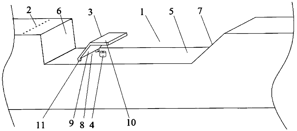
[0043] A scramjet engine includes a supersonic combustion chamber, and the ignition device in the supersonic concave cavity combustion chamber described in any one of the above technical solutions is arranged in the supersonic combustion chamber.

[0044] When the horizontal fuel injection scheme upstream of the concave cavity is adopted, the location of the bottom wall of the cavity with a local fast velocity occurs at the rear edge of the cavity, where the local fuel equivalence ratio is also high; while the position of the bottom wall of the cavity with a local slow velocity usually Occurs at the front and center of the cavity where the local fuel equivalent is relatively low. Therefore, when the fuel flows through the ignition position of the bottom wall of the concave cavity with the airflow, it is difficult to ensure that the local velocity and local equivalence ratio are both suitable, and the problems of difficult ignition and flameout are prone to occur. In the presen...


PUM


Abstract

The invention provides an ignition device in a supersonic concave cavity combustion chamber and a super-combustion stamping engine. The supersonic combustion chamber is internally provided with a fuelinjection hole and a concave cavity, the fuel injection hole is arranged at the upper stream of the concave cavity, and the fuel injected through the fuel injection hole propagates in the direction of the supersonic airflow propagation in a main flow channel of the supersonic combustion chamber; and a flow guide plate is obliquely arranged on the bottom wall of the concave cavity in the directionof the supersonic airflow propagation in the main flow channel, the lower end of the flow guide plate is connected to the bottom wall of the concave cavity, a gap is formed in the lower end of the flow guide plate, and a spark plug used for ignition is arranged on the portion, below the inner side of the flow guide plate, of the bottom wall of the concave cavity. According to the ignition device,the flow guide plate is applied to the interior of the concave cavity so as to improve the local flow rate and the equivalence ratio in the concave cavity, so that the ignition enhancement effect isachieved.

Description

technical field [0001] The invention relates to the technical field of scramjet design, in particular to an ignition device in a supersonic cavity combustion chamber and a scramjet. Background technique [0002] Concave flame stabilizers are widely used in scramjet combustion chambers. The supersonic airflow flowing through the concave cavity will form a recirculation zone in the concave cavity, which can keep the flame in it all the time, and continue to ignite the upstream fuel as a new ignition source, so as to achieve flame stabilization. The concave cavity can integrate fuel injection, mixing enhancement and flame stabilization in the supersonic combustion chamber, and plays an important role in improving the performance of the scramjet engine. [0003] Fuel injection / ignition / flame stabilization / cooling integrated concave cavity, which is common in engineering at present, includes the integration of fuel injection, ignition, and flame stabilization, with the concave c...

Claims


Application Information

Patent Timeline
Patent Type & Authority Patents(China)
IPC IPC(8): F23R3/28
CPCF23R3/28
Inventor 蔡尊朱家健汪洪波孙明波
Owner NAT UNIV OF DEFENSE TECH
Why Eureka
Try Eureka