Afterburner oil spraying device with high fuel oil regulation ratio

An afterburner and fuel adjustment technology, which is applied in the field of aviation power, can solve the problems of difficult debugging of joint matching work and high complexity of the oil circuit system, and achieve stable combustion, reduce system complexity, and reduce complexity.

Active Publication Date: 2020-02-21
SICHUAN AEROSPACE ZHONGTIAN POWER EQUIP CO LTD
View PDF6 Cites 2 Cited by
  • Summary
  • Abstract
  • Description
  • Claims
  • Application Information

AI Technical Summary

Problems solved by technology

[0005] Based on the above problems, the present invention provides an afterburner fuel injection device with a high fuel adjustment ratio, which solves the problems of high complexity of the existing engine afterburner, control system, and oil circuit system and difficult debugging of joint matching work To solve the problem, the fuel injection device can work reliably under the condition of high turndown ratio, and the afterburner can realize high-efficiency and stable combustion in a wide flow range

Method used


Image

  • Afterburner oil spraying device with high fuel oil regulation ratio
  • Afterburner oil spraying device with high fuel oil regulation ratio
  • Afterburner oil spraying device with high fuel oil regulation ratio

Examples


Embodiment 1

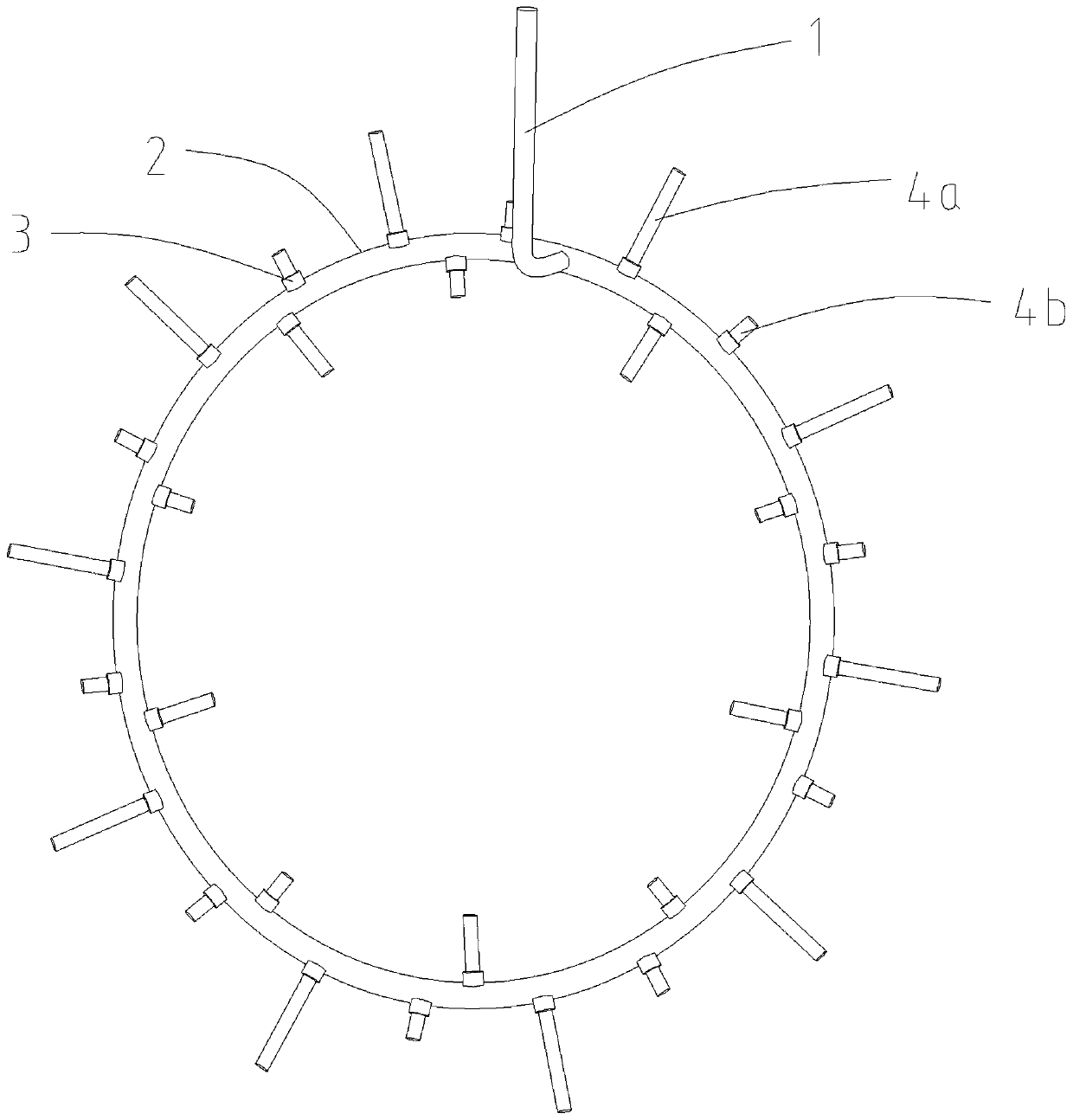
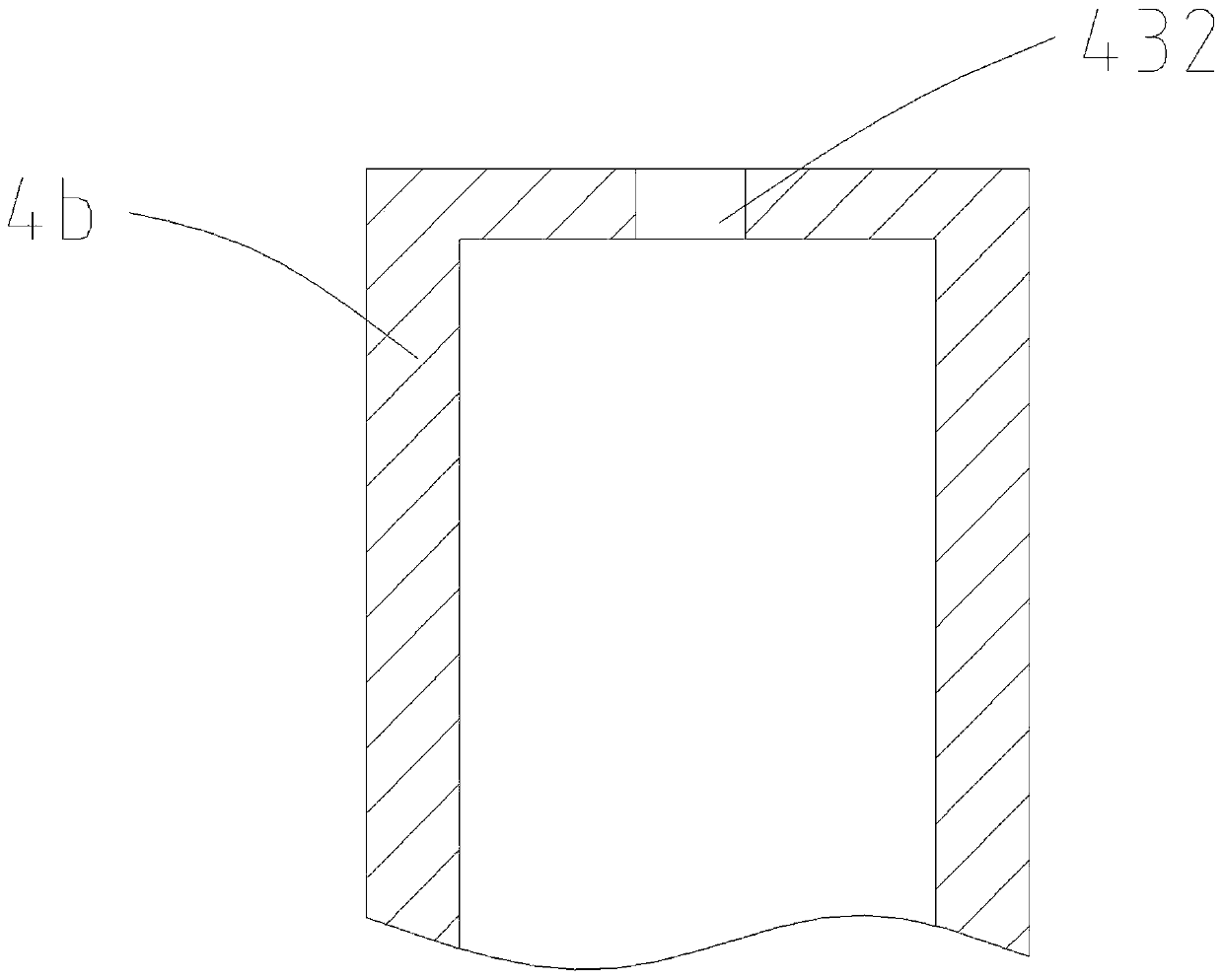
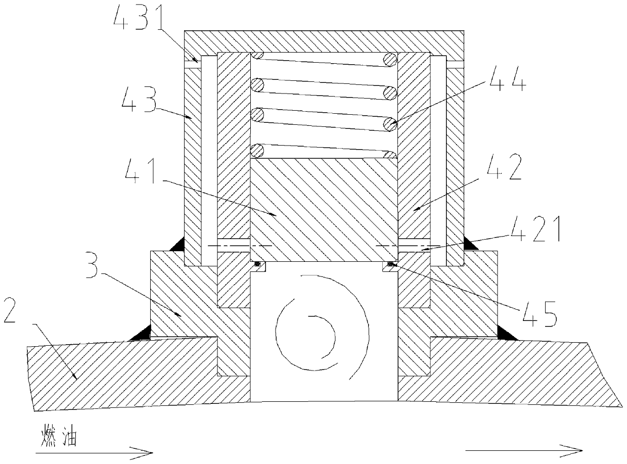
[0035] see Figure 1~6 , an afterburner fuel injection device with a high fuel adjustment ratio, comprising a ring pipe 2 and an oil inlet pipe 1 connected to the ring pipe 2, the inner and outer sides of the ring pipe 2 are provided with a plurality of tubular pipes around its circumferential direction Large fuel injection rod 4a, small fuel injection rod 4b, one end face of small fuel injection rod 4b away from ring pipe 2 is sealed and provided with first fuel injection nozzle 432, large fuel injection rod 4a includes the inner wall of fuel injection rods arranged at adjacent intervals 42 and the outer wall of the fuel injection rod 43, the inner wall of the fuel injection rod 42 and the outer wall 43 of the fuel injection rod are sealed away from one end face of the ring pipe 2, and the inner wall of the oil spray rod 42 is connected with the inner cavity of the ring pipe 2, and the outer wall of the oil spray rod 43 is connected with the ring pipe 2 Outer connection, the ...

Embodiment 2

[0038] This embodiment is further optimized on the basis of implementation 1, specifically:

[0039] A plurality of large oil injection rods 4a are evenly spaced on the inner and outer sides of the ring pipe 2 around its circumference, and small oil injection rods 4b are arranged between adjacent large oil injection rods 4a. The large oil injection rods 4a and the small oil injection rods 4b are alternately arranged at intervals.

[0040] As a preferred manner, the large oil injection rod 4a, the small oil injection rod 4b and the ring pipe 2 are all connected through the tubular adapter seat 3 . The conversion seat is tubular, and is connected with the ring pipe 2 by welding, and the conversion seat communicates with the inner cavity of the ring pipe 2, which avoids the problem of poor consistency in the installation and connection of the large fuel injection rod 4a, the small fuel injection rod 4b and the ring pipe 2.

[0041] As a preferred manner, the inner wall 42 of the l...


PUM


Abstract

The invention relates to the technical field of aviation power, and discloses an afterburner oil spraying device with a high fuel oil regulation ratio. The afterburner oil spraying device comprises anannular pipe, an oil inlet pipe, an adapter seat and oil spraying rods, wherein large oil spraying rods and small oil spraying rods are arranged on the inner side and the outer side of the annular pipe correspondingly. Each large oil spraying rod comprises an oil spraying rod inner wall and an oil spraying rod outer wall, the oil spraying rod inner walls and the oil spraying rod outer walls are connected with the adapter seat, a boss is fixedly arranged on the inner side of each oil spraying rod inner wall, a stop block is arranged on the upper side of each boss, a compressed spring is arranged on each stop block, oil passing holes communicating with the oil spraying rod outer walls are formed in the oil spraying rod inner walls on the annular sides of the stop blocks, and second oil nozzles communicating with the outer sides of the oil spraying rod inner walls are arranged on the outer annular sides of the oil spraying rod outer walls. According to the afterburner oil spraying device, the problems of high complexity and difficult joint matching work debugging of an existing engine afterburner, a control system and an oil way system can be solved, reliable operation of the oil spraying device under the condition of high regulation ratio can be realized, and efficient and stable combustion of an afterburner in a wide flow range can be realized.

Description

technical field [0001] The invention relates to the technical field of aerodynamics, and is specifically applied to an afterburner of a small turbojet engine, in particular to an afterburner fuel injection device with a high fuel adjustment ratio. Background technique [0002] The aeroengine with an afterburner has a larger thrust range, and the greater the thrust, the more complex the oil circuit system of the afterburner. At present, the aeroengine with the smallest thrust class has three oil circuits in its afterburner: the starting oil circuit, the first oil circuit used in the small afterburner and intermediate afterburner states, and the second oil circuit used in the full afterburner state. The starting oil circuit is only used during afterburner. These oil circuits match the complex control sequence and are opened and used in different stages. As the thrust of the engine increases, the fuel system becomes more complex, with as many as 10 oil circuits, which increas...

Claims


Application Information

Patent Timeline
Patent Type & Authority Applications(China)
IPC IPC(8): F23R3/28
CPCF23R3/28
Inventor 周君辉宋勇陈溯刘驰王丹丹
Owner SICHUAN AEROSPACE ZHONGTIAN POWER EQUIP CO LTD
Why Eureka
Try Eureka