
Broadband wide-angle frequency selective surface radome

A technology of frequency selective surface and radome, which is applied in the direction of antenna, antenna parts, radiating unit cover, etc., can solve the problems of low dielectric constant, poor strength and mechanical properties, etc., and achieve a wide range of angles, low cost, relatively The effect of bandwidth

Active Publication Date: 2020-02-21
CHANGCHUN INST OF OPTICS FINE MECHANICS & PHYSICS CHINESE ACAD OF SCI
View PDF18 Cites 13 Cited by
  • Summary
  • Abstract
  • Description
  • Claims
  • Application Information

AI Technical Summary

Problems solved by technology

Whether it is a radome with a half-wave wall or a multi-layer wall, the design principle of its wave transmission is based on electromagnetic wave interference, which will inevitably lead to the radome only meeting the requirements of high wave transmission at specific angles and characteristic frequency points. In addition, high Wave penetration requires that the radome dielectric material has a very low dielectric constant. Therefore, only foam, foam-like or porous materials with low dielectric constant are used as wave-transmissive materials, but the strength and mechanical properties of such materials are relatively low. Poor, a single material of this type cannot meet the mechanical and other performance requirements, so a multi-layer wall structure must be used to meet the bandwidth requirements

Method used


Image

  • Broadband wide-angle frequency selective surface radome
  • Broadband wide-angle frequency selective surface radome
  • Broadband wide-angle frequency selective surface radome

Examples


Embodiment Construction

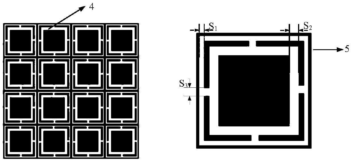
[0027] The following combination Figure 1-7 Specifically, a wide-band wide-angle frequency-selective surface radome provided by the present invention is described.

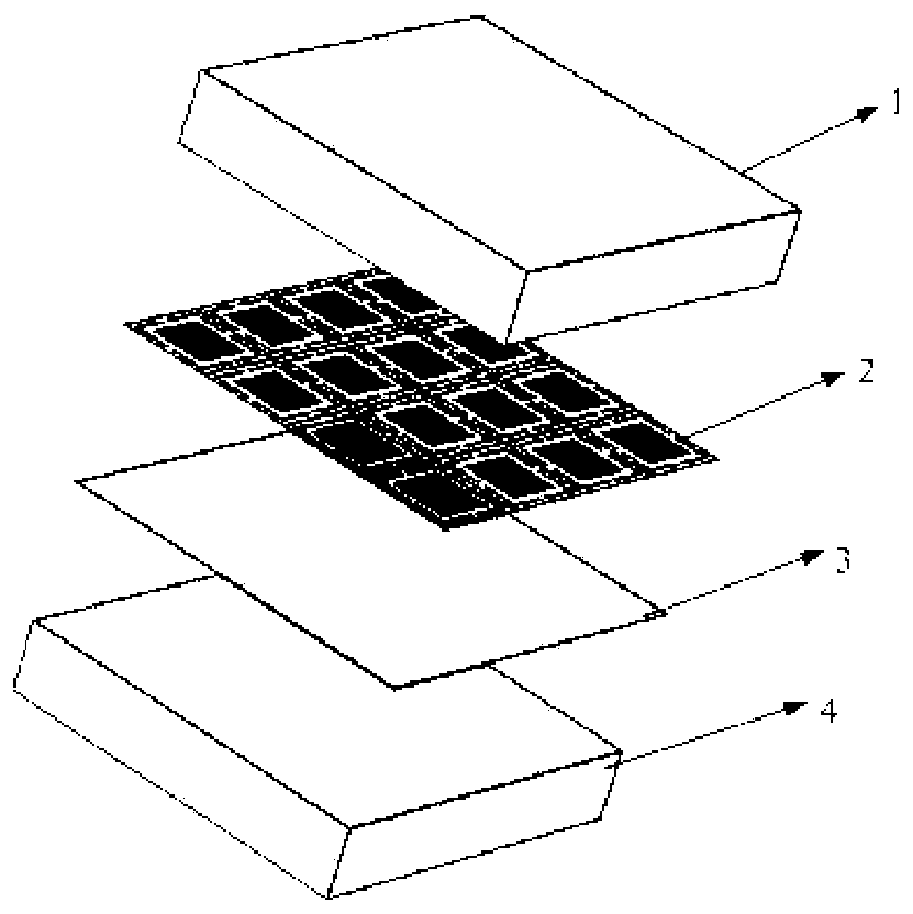
[0028] Such as figure 1 As shown, the present invention provides a wide-band wide-angle frequency selection surface radome, which is formed by arranging a plurality of basic unit arrays, and the basic unit includes a first dielectric layer 1, a second dielectric layer 2, a frequency selective Surface layer 3 and third dielectric layer 4. The second dielectric layer 2 is a supporting dielectric layer, which is the metal supporting layer of the frequency selective surface layer 3 .

[0029] As a preferred embodiment of the present invention, the material properties and thickness of the first dielectric layer 1 and the third dielectric layer 4 in the present invention are consistent; the first dielectric layer 1 and the third dielectric layer 4 are loaded symmetrically, and the frequency The surface layer 3 is se...


PUM

PropertyMeasurementUnit
Physical thicknessaaaaaaaaaa
Arm lengthaaaaaaaaaa

Abstract

The invention belongs to the technical field of stealth technology and radar antennas, and particularly relates to a broadband wide-angle frequency selective surface radome, which is formed by arranging a plurality of basic units in an array mode. Each basic unit comprises a first dielectric layer, a second dielectric layer, a frequency selective surface layer and a third dielectric layer, which are sequentially arranged. The dielectric layers are symmetrically loaded and form the Chebyshev impedance converter with the frequency selective surface layers, so that the problems of narrow wave-transparent frequency band, low wave-transparent rate and unstable angle of the radome are solved; meanwhile, the frequency selective surface layer is formed by utilizing the metamaterial design principle; the radome is formed by arranging the basic units periodically in the form of a square, and comprises a uniquely designed miniaturized sub-wavelength periodic pattern; and compared with a multi-layer radome loaded with a metal mesh, a multi-layer metamaterial surface coupling form and other forms of frequency selective surfaces, the radome is wider in high-wave-transmission relative bandwidth and wider in angle application range, and is simple in structure and low in cost.

Description

technical field [0001] The invention belongs to the field of stealth technology and radar antenna technology, in particular to a wide-band and wide-angle frequency selection surface radome. Background technique [0002] In the traditional radome design, the frequency band of the radome is relatively narrow (1-3%), and the radome with a single-layer half-wave wall structure can easily meet its electrical performance requirements. However, for broadband radome used in a certain frequency range, A, B, and C sandwich wall structures are commonly used. The A sandwich structure consists of a low dielectric constant, low loss, and low-density intermediate core layer (foam or honeycomb) structure) and two relatively dense and thin surface layers (skin) inside and outside. The B sandwich structure is composed of two low dielectric constant, low density surface layers and a relatively dense core layer; the C sandwich structure (five layers) is composed of two A sandwich structures. ...

Claims


Application Information

Patent Timeline
IPC IPC(8): H01Q1/42B32B15/20B32B27/28B32B27/32B32B27/38B32B27/42B32B9/00B32B3/24B32B27/06B32B33/00
CPCB32B3/266B32B9/00B32B9/005B32B15/20B32B27/06B32B27/281B32B27/322B32B27/38B32B27/42B32B33/00H01Q1/422
Inventor 徐念喜高劲松单冬至宋乃涛陈新
Owner CHANGCHUN INST OF OPTICS FINE MECHANICS & PHYSICS CHINESE ACAD OF SCI
Learn More