
Heat dissipation rainproof switch cabinet

A switchgear and rainproof technology, applied in the field of switchgear, can solve the problems of damage to electronic components, waste of internal space of the cabinet, inconvenient heat dissipation of the cabinet, etc., to achieve high-efficiency rainproof performance, easy installation and setting, and good rainproof effect. Effect

Pending Publication Date: 2020-02-21
雷朋电气集团有限公司
View PDF0 Cites 0 Cited by
  • Summary
  • Abstract
  • Description
  • Claims
  • Application Information

AI Technical Summary

Problems solved by technology

[0002] Switchgear is a kind of electrical equipment. Its main function is to open and close, control and protect electrical equipment during the process of power generation, transmission, distribution and power conversion in the power system. When the switchgear is in use, its internal electronic components It will generate heat, and if the generated heat is not discharged in time, it may affect the operation of the electronic components inside the cabinet. The disorderly installation and arrangement of electronic components inside the cabinet will not only waste the space inside the cabinet, but also cause It makes it inconvenient to dissipate heat inside the cabinet. The switchgear is always installed outdoors. The outdoor switchgear has high requirements for its rainproof performance. Rainwater inside the cabinet will cause damage to the electronic components inside the cabinet. Therefore, a new solution is needed now.

Method used


Image

  • Heat dissipation rainproof switch cabinet
  • Heat dissipation rainproof switch cabinet
  • Heat dissipation rainproof switch cabinet

Examples


Embodiment 1

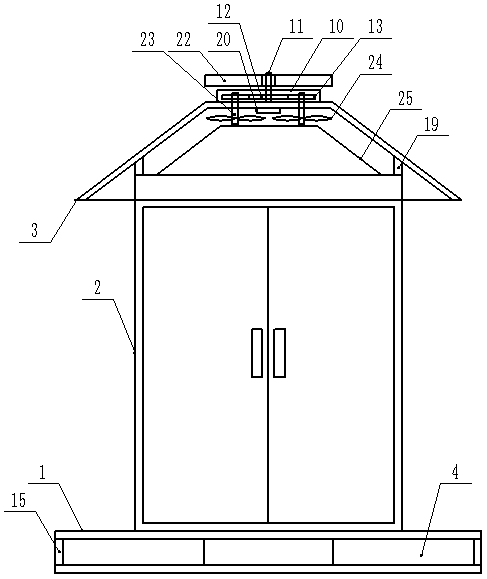
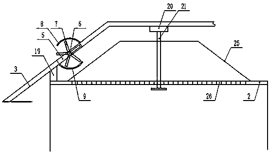
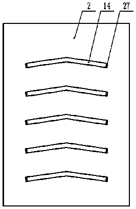
[0014] Example 1: see figure 1 , figure 2 , image 3 , Figure 4 Now, a heat dissipation and rainproof switch cabinet provided by the present invention is described, including a base 1, a cabinet body 2 provided on the upper end of the base 1, and a rainproof cover 3 provided on the top of the cabinet body 2. The inner cavity of the base 1 There is a cross-shaped ventilation slot 4, and a strip-shaped opening 5 is opened on the outer end wall of the rainproof cover body 3. A circular shaft 6 is provided on the middle side of the inner end of the strip-shaped opening 5 and moves along its length direction. The outer equal arc of the circular shaft 6 is evenly provided with the first deflector 7, the outer end wall of the rainproof cover body 3 is provided with an arc-shaped rainproof frame body 8, and the inner end wall of the rainproof cover body 3 An arc-shaped rain-proof frame body 9 is provided, and a protective casing 10 is provided at the upper end of the rainproof co...

Embodiment 2

[0015] Example 2: see figure 1 , figure 2 , Figure 4 , the present invention provides a description of a heat dissipation and rainproof switchgear, the four sides of the cross-shaped ventilation slot 4 are designed with openings, and the ports on the four sides of the cross-shaped ventilation slot 4 are respectively provided with first Dust-proof net cover 15, the middle side of the inner end of the cross-shaped ventilation groove 4 is vertically movable and provided with a third transmission shaft 16, and the top end of the third transmission shaft 16 in the vertical direction is movable and extends into the bottom of the cabinet body 2 In the inner cavity, the second deflector 17 is uniformly arranged on the outside of the bottom end of the third transmission shaft 16, and the first cooling fin 18 is evenly arranged on the outside of the top end, and the first cooling fin 18 is arranged on the cabinet. The inner cavity at the bottom of the body 2, the horizontal cross-se...

Embodiment 3

[0016] Embodiment 3: see figure 1 , figure 2 Now, a heat dissipation and rainproof switchgear provided by the present invention will be described. The top end of the first transmission shaft 11 in the vertical direction moves through the inner top wall of the protective shell 10, and the first transmission shaft 11. A third deflector 22 is evenly arranged on the outside of the extended end with equal arcs. The top ends of the second transmission shaft 23 in the vertical direction respectively move into the protective housing 10. The second transmission shaft 23 extends The end of the inlet end is respectively covered with a driven transmission gear 13, and the outside of the first transmission shaft 11 and the corresponding position of the driven transmission gear 13 are covered with a driving transmission gear 12, and the driving transmission gear 12 and the driven transmission gear 13 are connected to each other. The meshing transmission between them, the bottom end of the...


PUM


Abstract

The invention discloses a heat dissipation rainproof switch cabinet. The switch cabinet comprises a pedestal, a cabinet body and a rainproof cover body, wherein the cabinet body is arranged at an upper end of the pedestal, and the rainproof cover body is arranged at a top of the cabinet body. A cross-shaped ventilation groove is arranged in an inner cavity of the pedestal. A strip-shaped through hole is arranged in an outer end wall of the rainproof cover body. A circular shaft is movably arranged on a middle side of an inner end of the strip-shaped through hole along a length direction. Firstflow deflectors are evenly arranged on an outer portion of the circular shaft at an equal radian. An arc-shaped rainproof frame body is arranged on the end wall of the outer side of the rainproof cover body. An arc-shaped rain sheltering frame body is arranged on the end wall of the inner side of the rainproof cover body. The upper end of the rainproof cover body is provided with a protective shell, a middle side of the upper end of the rainproof cover body is vertically and movably provided with a first transmission shaft, a driving transmission gear and a driven transmission gear are arranged in the protective shell, an inner top of the rainproof cover body is uniformly and vertically provided with second transmission shafts, and an outer end wall of the cabinet body is uniformly provided with ventilation pipes.

Description

technical field [0001] The invention relates to the field of switch cabinets, in particular to a heat dissipation and rainproof switch cabinet. Background technique [0002] Switchgear is a kind of electrical equipment. Its main function is to open and close, control and protect electrical equipment during the process of power generation, transmission, distribution and power conversion in the power system. When the switchgear is in use, its internal electronic components It will generate heat, and if the generated heat is not discharged in time, it may affect the operation of the electronic components inside the cabinet. The disorderly installation and arrangement of electronic components inside the cabinet will not only waste the space inside the cabinet, but also cause It makes it inconvenient to dissipate heat inside the cabinet. The switchgear is always installed outdoors. The outdoor switchgear has high requirements for its rainproof performance. Rainwater inside the ca...

Claims


Application Information

Patent Timeline
Patent Type & Authority Applications(China)
IPC IPC(8): H02B1/30H02B1/28H02B1/56H02B1/34
CPCH02B1/28H02B1/30H02B1/34H02B1/565
Inventor 钟新国耿昌鹏
Owner 雷朋电气集团有限公司
Learn More