Temperature sensor and heating appliance component

A technology for temperature sensors and heating appliances, which is applied in the field of temperature sensors and heating appliance components, can solve the problems of complex assembly, many structural parts, and affecting production efficiency, and achieve the reduction of the number of parts, the reduction of installation steps, and the high assembly efficiency Effect

Pending Publication Date: 2020-02-25
FOSHAN SHUNDE MIDEA ELECTRICAL HEATING APPLIANCES MFG CO LTD
View PDF0 Cites 0 Cited by
  • Summary
  • Abstract
  • Description
  • Claims
  • Application Information

AI Technical Summary

Problems solved by technology

[0002] On existing heating appliances such as induction cooker, a temperature sensor is provided for measuring the temperature of the pan. For the structure of the temperature sensor, such as figure 1 As shown, in the assembly process, it is necessary to install the temperature-sensing component 10' and other parts into the housing 20' of the temperature sensor from the bottom up, and then use the sleeve 40' to press the temperature-sensing component 10' upward, and then use the limit spring to 30' is assembled with the shell 20' and is pushed upward against the sleeve 40' to limit it so that the sleeve 40' keeps pressing the temperature-sensitive part 10', preventing parts such as the temperature-sensitive part 10' inside the shell 20' from being pulled out downwards , this kind of structure has many parts, complex assembly, and many assembly processes, which affect production efficiency

Method used


Image

  • Temperature sensor and heating appliance component
  • Temperature sensor and heating appliance component
  • Temperature sensor and heating appliance component

Examples


specific Embodiment 1

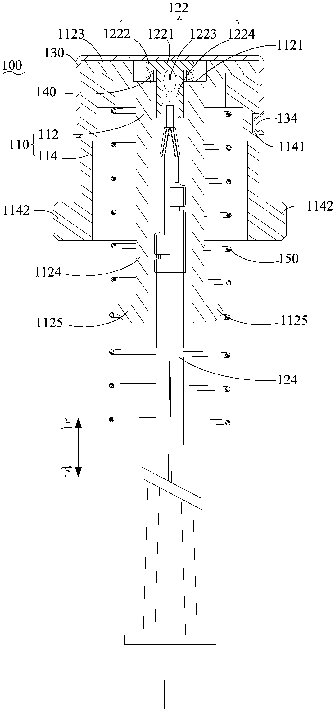
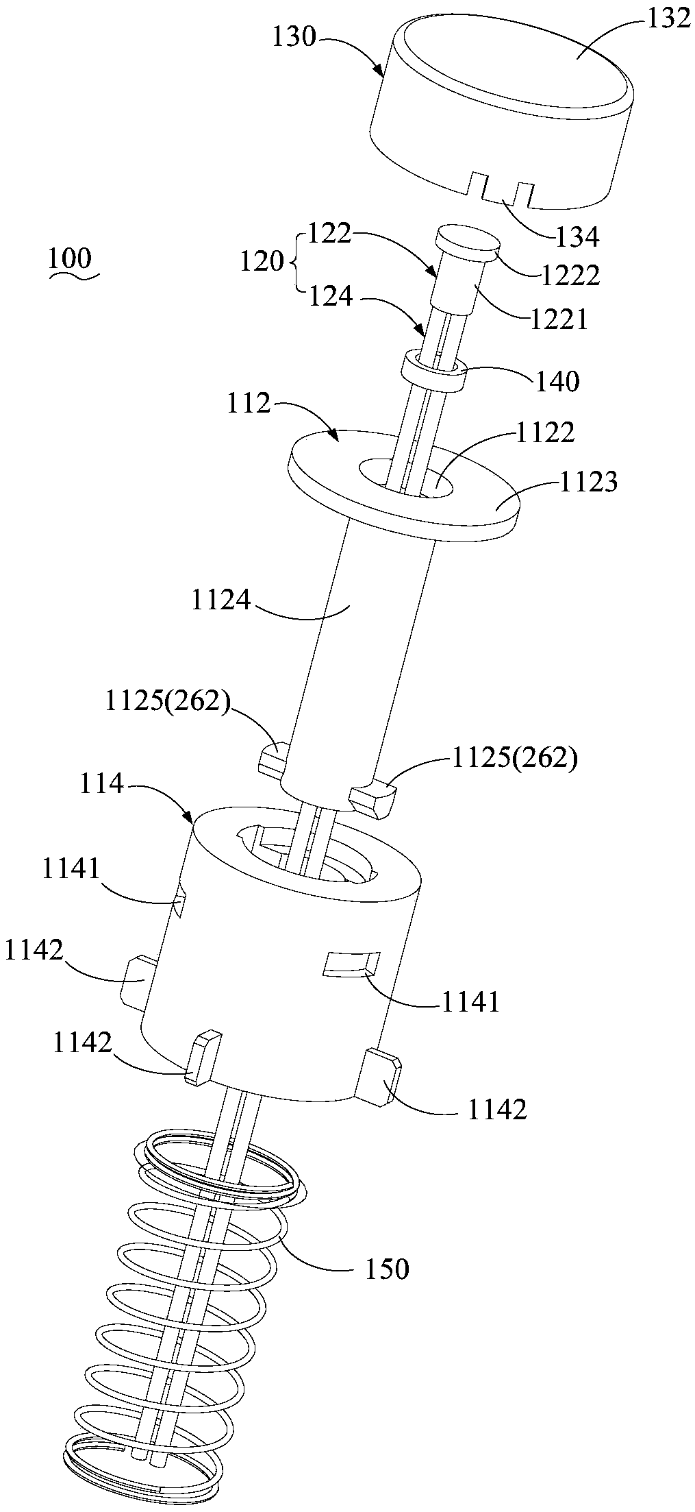
[0104] Specific embodiment one (such as figure 2 and image 3 shown)

[0105] The temperature sensor 100 includes a bracket 110 , a temperature sensing member 120 , a temperature sensing cap 130 , an elastic buffer member 140 and a spring 150 .

[0106] The temperature sensing member 120 includes a lead wire 124 and a temperature sensing module 122. The temperature sensing module 122 is preferably a thermistor module, and specifically includes a housing 1221, a temperature sensing member 1223 and a packaging material 1224. The housing 1221 is preferably a ceramic sleeve, and the housing 1221 is provided with a flange 1222, the temperature sensitive member 1223 is located in the housing 1221, the packaging material 1224 is located in the housing 1221 and the temperature sensitive member 1223 is encapsulated and fixed. It is electrically connected to the lead wire 124 .

[0107] The bracket 110 includes a bracket body 112 and a base 114. The center of the bracket body 112 is...

specific Embodiment 2

[0109] Specific embodiment two (such as Figure 4 to Figure 9 shown)

[0110] The heating appliance assembly is an induction cooker, including the heating appliance 200 and the temperature sensor 100 in the first embodiment.

[0111] The heating appliance 200 includes a panel 210, a coil disk support 220 and a base 230. The temperature sensor 100 is mounted on the coil disk support 220, and the coil disk support 220 is mounted on the base 230. The panel 210 is preferably a microcrystalline plate, and the panel 210 is located on the coil disk. Above the bracket 220 and the panel 210 is provided with a through hole 212 , the temperature sensor 100 passes upward through the through hole 212 and protrudes to the outside of the panel 210 , wherein the part of the temperature sensor 100 located in the through hole 212 is a clearance fit with the through hole 212 .

[0112] A sealing ring 240 is arranged between the panel 210 and the coil disk support 220. There is a glue groove on t...


PUM


Abstract

The invention provides a temperature sensor and heating appliance component. The temperature sensor comprises a bracket on which a support level is arranged; a temperature sensing member with a temperature sensing module, wherein the temperature sensing module is arranged on the bracket and supported by the support level; and a temperature sensing cap covered on the bracket and connected with thebracket through an assembling structure, wherein the temperature sensing cap is used for backstopping the temperature sensing module and limiting the temperature sensing module on the support level. Through the temperature sensor provided by the scheme, the modular assembling fixation among the temperature sensing cap, the bracket and the temperature sensing member can be realized without utilizing a limiting snap spring, a sleeve and like parts, the number of the parts of the product is reduced, the mounting steps are reduced, and the assembling efficiency of the product is higher.

Description

technical field [0001] The present invention relates to the field of heating appliances, in particular, to a temperature sensor and a heating appliance assembly. Background technique [0002] On existing heating appliances such as induction cookers, a temperature sensor is provided for measuring the temperature of the pot. For the structure of the temperature sensor, such as figure 1 As shown, in the assembly process, it is necessary to load the temperature sensing component 10' and other parts into the housing 20' of the temperature sensor from bottom to top, and then use the sleeve 40' to press the temperature sensing component 10' upward, and then use the limit circlip 30' is assembled with the outer casing 20', and pushes upward against the sleeve 40' to limit it, so that the sleeve 40' keeps pressing the temperature-sensing component 10', preventing parts such as the temperature-sensing component 10' inside the outer casing 20' from being pulled down. , This kind of st...

Claims


Application Information

Patent Timeline
Patent Type & Authority Applications(China)
IPC IPC(8): A47J36/24A47J36/00G01K1/14G01K1/16
CPCA47J36/2483A47J36/00G01K1/14G01K1/16G01K2207/00
Inventor 杨毅苏畅王帅罗绍生
Owner FOSHAN SHUNDE MIDEA ELECTRICAL HEATING APPLIANCES MFG CO LTD
Why Eureka
Try Eureka