
Shaft workpiece boring and milling clamping auxiliary adjusting device

A technology for shaft workpieces and adjustment devices, which is applied in positioning devices, metal processing machinery parts, manufacturing tools, etc., can solve the problems of easy occurrence of safety accidents, lifting force, time-consuming and labor-intensive, etc., so as to reduce lifting operations and labor intensity. , Adjust the effect of high precision

Pending Publication Date: 2020-02-25
石钢京诚装备技术有限公司
View PDF0 Cites 0 Cited by
  • Summary
  • Abstract
  • Description
  • Claims
  • Application Information

AI Technical Summary

Problems solved by technology

The adjustment value of the center height of the workpiece needs to calculate the thickness of the required backing plate according to the angle of the ordinary V-shaped shim iron, and the thickness of the backing plate is usually several common specifications, and the approximate thickness can be obtained through various combinations. This method Time-consuming and labor-intensive, and the accuracy is not high; and because the weight of the workpiece is large, the crane needs to cooperate when adjusting the backing plate, the lifting is laborious, and safety accidents are prone to occur. Considering safety and operation, the number of lifting should be reduced

Method used


Image

  • Shaft workpiece boring and milling clamping auxiliary adjusting device
  • Shaft workpiece boring and milling clamping auxiliary adjusting device
  • Shaft workpiece boring and milling clamping auxiliary adjusting device

Examples


Embodiment Construction

[0028] Below in conjunction with accompanying drawing, the present invention will be further described by examples.

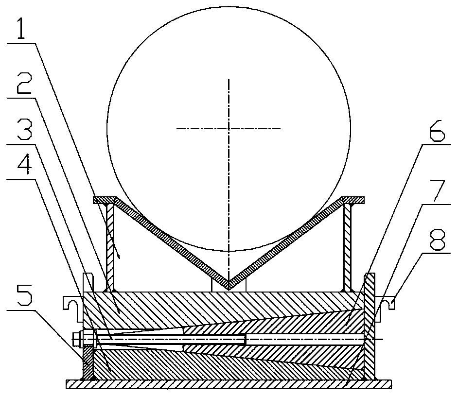
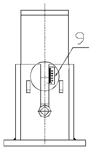
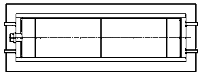
[0029] Refer to attached Figure 1-11 , an auxiliary adjusting device for boring, milling and clamping of shaft workpieces, comprising a V-shaped pad iron 1, a movable inclined iron 2, a fixed inclined iron 4, an adjusting bolt 3, a baffle plate 5 and an adjusting inclined iron 6, the movable inclined iron 2 and the fixed inclined iron The section of the inclined iron 4 is a right triangle, the section of the adjustable inclined iron 6 is an isosceles trapezoid matched with the movable inclined iron 2 and the fixed inclined iron 4, and the adjustable inclined iron 6 is arranged between the movable inclined iron 2 and the fixed inclined iron 4 Between them, the movable inclined iron 2, the adjusting inclined iron 6 and the fixed inclined iron 4 are stacked up and down together to form a cuboid, and baffles 5 are arranged around the cuboid, the V-shaped parallel ...


PUM

PropertyMeasurementUnit
Vertex angleaaaaaaaaaa

Abstract

The invention relates to a shaft workpiece boring and milling clamping auxiliary adjusting device, and belongs to the technical field of machining auxiliary equipment. According to the technical scheme, the cross sections of a movable ramp iron (2) and a fixed ramp iron (4) are of right triangle shapes, the cross section of an adjusting ramp iron (6) is of isosceles trapezoid shape matched with the movable ramp iron (2) and the fixed ramp iron (4), and the adjusting ramp iron (6) is arranged between the movable ramp iron (2) and the fixed ramp iron (4); and the movable ramp iron (2), the adjusting ramp iron (6) and the fixed ramp iron (4) are stacked up and dowm together to form a cuboid, the periphery of the cuboid is provided with a baffle, a V-shaped cushion iron (1) is fixed on the movable ramp iron (2), an adjusting bolt (3) is in threaded connection with the adjusting ramp iron (6), and the baffle (5) is provided with sliding grooves matched with the adjusting bolt (3) and the movable ramp iron (2). The shaft workpiece boring and milling clamping auxiliary adjusting device has the beneficial effects that the stability of workpiece clamping can be ensured, the adjustment is convenient, the adjustment precision is high, and the boring and milling machining requirements can be met.

Description

technical field [0001] The invention relates to an auxiliary adjustment device for boring and milling chucking of shaft workpieces, belonging to the technical field of machining auxiliary equipment. Background technique [0002] In the machining workshop, some large stepped shaft workpieces need to punch center holes at both ends of the workpiece before turning and clamping, and some shaft workpieces need to bore and mill blind and deep holes on the body according to the drawing requirements. The above two workpieces are in When machining and clamping on the boring machine table, first of all, ensure that the workpiece is placed stably and firmly on the boring machine table; secondly, it is necessary to ensure that the axis of the workpiece after clamping is parallel to the boring machine table, so that the workpiece can be turned. The machining allowance, the inner hole and the outer circle meet the coaxiality requirements when milling and boring the hole. [0003] In orde...

Claims


Application Information

Patent Timeline
IPC IPC(8): B23Q3/00B23Q3/18
CPCB23Q3/00B23Q3/18
Inventor 王竹叶
Owner 石钢京诚装备技术有限公司
Learn More