Air duct structure and air conditioning system

An air duct and air inlet technology, which is applied in the field of air duct structure and air conditioning system, can solve the problems of small adjustable range of air coverage space, small air volume adjustment range, and small air outlet status, and achieves large adjustable range and air volume. The effect of large adjustment range and many air outlet states

Pending Publication Date: 2020-02-25
GREE ELECTRIC APPLIANCES INC
View PDF0 Cites 0 Cited by
  • Summary
  • Abstract
  • Description
  • Claims
  • Application Information

AI Technical Summary

Problems solved by technology

[0002] Air-conditioning equipment needs to be equipped with a diversion structure in the air duct structure to divert the outlet air, that is, to divide the air. However, the diversion structure is driven by the driving mechanism configured on the air-conditioning equipment, which has a complex structure and high cost. , under normal circumstances, the diversion structure can adjust the air outlet into three states, and the air outlet state can be realized less, and the air volume adjustment range is small, and the adjustable range of the air outlet coverage space is also small

Method used


Image

  • Air duct structure and air conditioning system
  • Air duct structure and air conditioning system
  • Air duct structure and air conditioning system

Examples


Embodiment 1

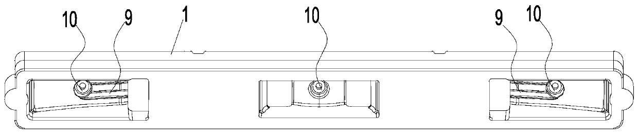
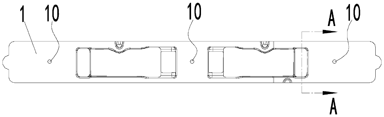
[0048] This embodiment provides an air duct structure for guiding and distributing air from an air conditioner. The air duct structure includes a housing 1 and a first block 2. One side of the housing 1 is provided with an air inlet. The other side of the casing 1 is provided with an air outlet, the air inlet corresponds to the air inlet side, and the air outlet corresponds to the air outlet side. The number of the first block 2 is at least two, and the first block 2 is arranged at the air outlet and divides the above air outlet into several sub-air outlets.

[0049] With this structure, the wind coming in from the air inlet will be blown out from different sub-air outlets, the first block 2 plays a role in guiding and diverting the wind, the number of the first block 2 is at least two, and all The first block 2 is installed in the middle of the air outlet, so that the number of sub-air outlets formed is at least three. Therefore, when the air duct structure provided by this e...

Embodiment 2

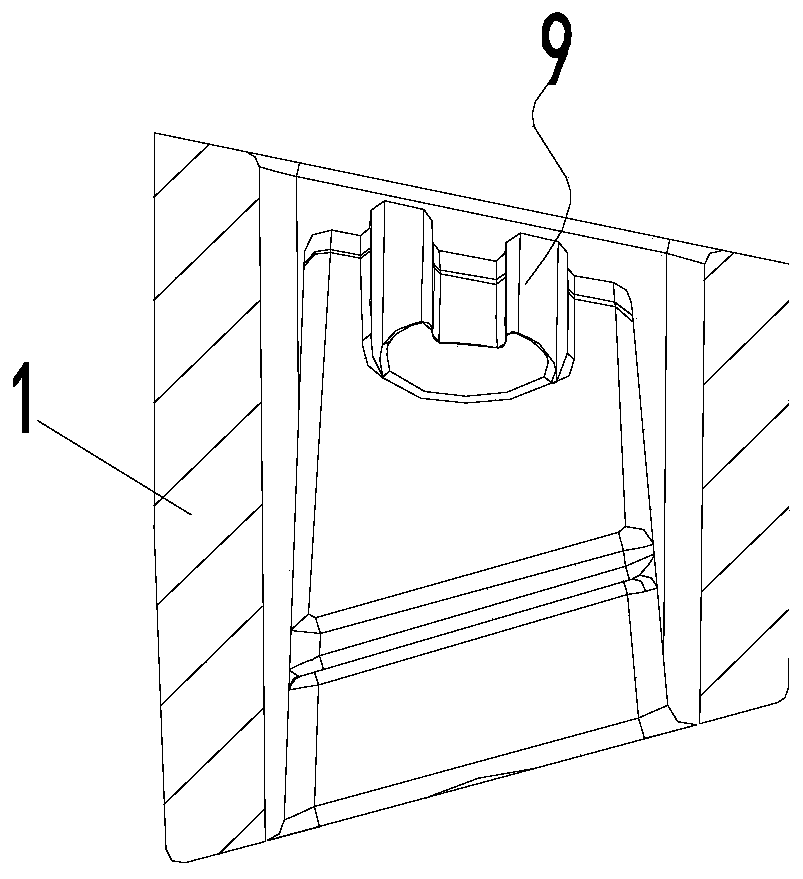
[0052] This embodiment is further improved on the basis of Embodiment 1. The air duct structure provided by this embodiment also includes a second block 6, which is located in the middle of the air inlet, so as to The air inlet is divided into two sub-air inlets with the same flow rate. It is worth noting that the above-mentioned second block 6 is a conical block, and the conical tip of the second block 6 faces the inside of the air duct structure. The second block 6 is integrally formed with the shell 1 and the first block 2, and the first block 2, the second block 6, and the shell 1 are structural members made of foam, specifically, the entire air duct The structure is cast using a mould. The second block 6 is also provided with the aforementioned screw holes 10 .

[0053] The number of the above-mentioned first block 2 is two, and the two first blocks 2 are symmetrically arranged at the above-mentioned air outlet, thereby dividing the air outlet into three sub-air outlets...

Embodiment 3

[0065] This embodiment is a more optimal implementation of the above-mentioned embodiment. In this embodiment, the side of the first block 2 close to the air inlet is defined as the windward surface 21. In the air duct structure provided by this embodiment, the first block The windward surface 21 on 2 is a curved surface inclined toward the housing 1, that is, the distance between the side of the curved surface close to the housing 1 and the air inlet is smaller than that of the side away from the housing 1.

[0066] With this structure, a smooth and even wind distribution effect can be obtained.

[0067] As the best implementation mode of this embodiment, in this embodiment, the above-mentioned curved surface (that is, the windward surface 21 on the first block 2) is a wave surface, specifically, the curved surface is composed of a first arc surface, a second arc surface and the third arc surface in sequence, the centers of the first arc surface and the third arc surface are ...


PUM


Abstract

The invention relates to an air duct structure and an air conditioning system, and belongs to the technical field of air conditioners. The air duct structure comprises a shell, at least two first blocks and a second block, wherein an air inlet is formed in one side of the shell, and an air outlet is formed in the other side of the shell; the first blocks are arranged at the air outlet and divide the air outlet into a plurality of sub air outlets; the second block is arranged in the middle position of the air inlet and divides the air inlet into two sub air inlets with the same flow rate; and the two first blocks are symmetrically distributed at the air outlet and divide the air outlet into three sub air outlets with the same flow rate. The air duct structure is adopted by the air conditioning system, and the air duct structure and the air conditioning system both have the advantages of more air outlet states and larger air outlet air volume adjustment range and larger air outlet coverage range.

Description

technical field [0001] The invention belongs to the technical field of air conditioning, and in particular relates to an air duct structure and an air conditioning system. Background technique [0002] Air-conditioning equipment needs to be equipped with a diversion structure in the air duct structure to divert the outlet air, that is, to divide the air. However, the diversion structure is driven by the driving mechanism configured on the air-conditioning equipment, which has a complex structure and high cost. , usually, the diversion structure can adjust the air outlet into three states, and there are fewer air outlet states that can be realized, and the air volume adjustment range is small, and the adjustable range of the air outlet coverage space is also small. Contents of the invention [0003] The invention provides an air duct structure, which is used to solve the technical problems in the prior art that the air duct structure has less air outlet states, a small air ...

Claims


Application Information

Patent Timeline
Patent Type & Authority Applications(China)
IPC IPC(8): F24F13/08F24F1/0014
CPCF24F1/0014F24F13/08
Inventor 陈良兴朱守朝黄传曦
Owner GREE ELECTRIC APPLIANCES INC
Why Eureka
Try Eureka