Connector with rapid wire locking structure and wire locking method thereof

A technology of connectors and wire locking, which is applied in the direction of connection, parts of connection devices, electrical components, etc., can solve problems such as misoperation of push rod external force, small range of locking wires, loose cables, etc., to achieve safe and reliable use, The effect of easy operation and small structure size

Active Publication Date: 2020-02-25
SUZHOU HUAZHAN SPACE APPLIANCE +1
View PDF14 Cites 3 Cited by
  • Summary
  • Abstract
  • Description
  • Claims
  • Application Information

AI Technical Summary

Problems solved by technology

[0007] In the prior art, although the push rod is used to drive the cam to rotate to drive the shrapnel to open the locking wire hole of the shrapnel, and then after the push rod is reset, the shrapnel loses the resisting force of the cam, so that the locking wire hole of the shrapnel is reset to clamp the cable end , but the push rod is used to drive the cam to press and fit outside the connector, the push rod is easily misoperated by external force, causing the cable to loosen
Moreover, the setting of the shrapnel locking thread is limited by the structure of the shrapnel, and the range of locking thread that can be applied is small

Method used


Image

  • Connector with rapid wire locking structure and wire locking method thereof
  • Connector with rapid wire locking structure and wire locking method thereof
  • Connector with rapid wire locking structure and wire locking method thereof

Examples


Embodiment 1

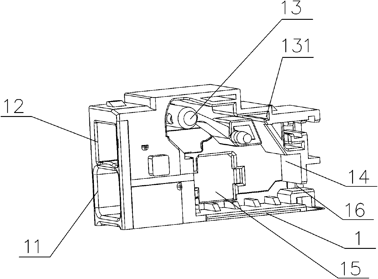
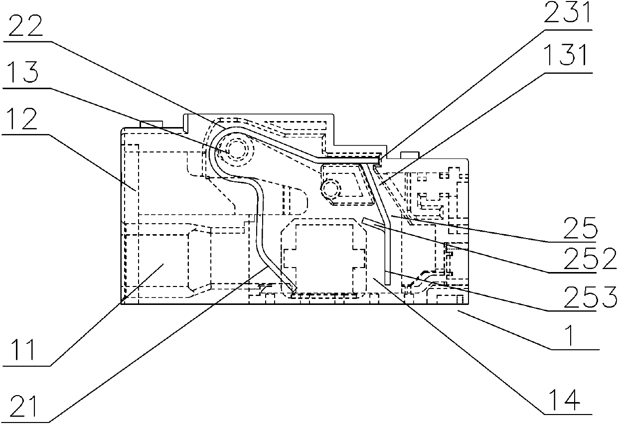
[0040] like Figure 1~Figure 6 As shown, a connector with a quick locking wire structure includes an insulating base 1, and a locking wire cavity 14 is provided on the insulating base 1, and a wire threading hole 11 and a reset slot 12 communicated with the locking wire cavity 14. The lock wire cavity 14 is provided with a conductor 3, a spring piece 2 for pressing against the cable 4, and a lock structure 25 that can be combined and locked with the spring piece 2, and the spring piece 2 and the lock structure 25 are an integral structure.

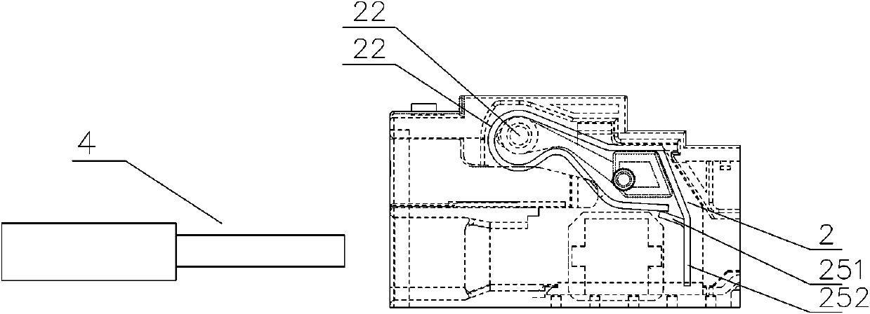
[0041] Specifically, the locking wire cavity 14 is provided with a positioning shaft 13 that penetrates into the arc surface 22 , and the elastic piece 2 includes a wire pressing arm 21 that is connected to one end of the arc surface 22 and is pressed against the surface of the cable 4 . The other end of the curved surface 22 is provided with a limit arm 1 23 , and a limit arm 2 251 of the locking structure 25 integrated with the limit arm...

Embodiment 2

[0045] like Figure 5 , Figure 7~Figure 12 As shown, on the basis of the first embodiment, the locking structure 25 and the elastic piece 2 are preferably set as two separate parts. The locking structure 25 includes a pivot end 255 pivotally arranged in the lock wire cavity 14, and the pivot end 255 A pivot hole sleeved on the pivot shaft 2 17 in the lock wire cavity 14 is used. One end of the pivot end 255 is provided with a lock groove 256 corresponding to the reset groove 12 and the wire pressing arm 21 , and a lock groove 256 is provided below the lock groove 256 Through hole, the size and shape of the structure opened by the through hole are matched with the structure of the locking buckle 53 provided at the end of the push block 5; A resilient piece 254 abutting against the locking wire cavity 14 is arranged on the outside; a tab 252 is arranged on the inside of the connection between the second limit arm 251 and the unlocking surface 253 , and the tab 252 and the unlo...


PUM


Abstract

The invention relates to a connector with a rapid wire locking structure, which comprises an insulating base. The insulating base is provided with a wire locking cavity and a threading hole communicated with the wire locking cavity, and the wire locking cavity is internally provided with a conductor and an elastic sheet which can swing back and forth relative to the conductor and is used for pressing a cable; the insulating base is further provided with a reset groove communicated with the wire locking cavity; a lock catch structure used for locking the elastic piece is further arranged in thewire locking cavity; and the lock catch structure is provided with a clamping tongue capable of being connected with the swinging elastic piece in a clamped mode and an unlocking face right oppositeto the threading hole. The connector provided by the invention can adapt to various cables and is provided with a rapid wire locking structure, and the operation of unlocking the cables can be easilyrealized. The cable is unlocked by pushing the elastic sheet; by adopting the structure that the elastic sheet and the lock catch are matched and self-locked, the wire locking and unlocking functionsof the elastic sheet are realized through the deformation of the elastic sheet; and the reset function is realized through the elasticity of the elastic sheet.

Description

technical field [0001] The invention relates to the technical field of wire-locking connectors, and can realize fast wire-locking and unlocking, and can meet the requirements of on-site wire-making. Background technique [0002] In the installation site of communication equipment or electronic and electrical equipment, it is often necessary to use on-site cable connectors, traditional on-site cable connectors, and traditional on-site cable locking structures in most cases are screw locking lines. [0003] In the prior art, for example, patent name: power connector (patent number: CN200420001515.5), a power connector is disclosed, which includes an insulating shell, a first terminal, a second terminal, a switch terminal and a jacking piece, The first terminal has a contact portion and a contact rod, the contact portion and the contact rod protrude into the accommodating space of the insulating housing, and the second terminal has a spring piece that protrudes into the accommo...

Claims


Application Information

Patent Timeline
Patent Type & Authority Applications(China)
IPC IPC(8): H01R13/502H01R13/627H01R13/629
CPCH01R13/502H01R13/627H01R13/629H01R4/48365
Inventor 张杰刘小彦何仲祺孙宝亮寇中辉
Owner SUZHOU HUAZHAN SPACE APPLIANCE
Why Eureka
Try Eureka