Automatic chicken raising equipment

An equipment and technology of chicken cages, which are applied in the poultry industry, applications, poultry cages or houses, etc., can solve the problems of inability to move forward, inconvenient personnel movement, and chicken cages occupying farm space, etc., to ensure the use effect, increase The number of chickens raised and the effect of easy promotion and use

Pending Publication Date: 2020-02-28
清农集团有限公司
View PDF10 Cites 1 Cited by
  • Summary
  • Abstract
  • Description
  • Claims
  • Application Information

AI Technical Summary

Problems solved by technology

[0002] At present, large-scale chicken farms in China have realized automatic feeding, but at present, most of them adopt a single-row structure, and only one side of the trough can be set up, resulting in chicken cages occupying the space of the farm and reducing the number of chickens to be fed.
At the same time, the current feeding mechanism cannot accurately control the amount of feed put into the trough, resulting in waste of feed or insufficient food for chickens
In addition, most of the current mobile trolleys are straddled on the chicken cage frame, and the wheels run directly on the ground. This not only occupies the passage space and causes inconvenience for personnel to move, but also has the possibility of being unable to move forward when encountering obstacles on the ground, which affects the use effect

Method used


Image

  • Automatic chicken raising equipment
  • Automatic chicken raising equipment
  • Automatic chicken raising equipment

Examples


Embodiment Construction

[0026] The specific implementation manners of the present invention will be further described in detail below in conjunction with the accompanying drawings and embodiments. The following examples are used to illustrate the present invention, but are not intended to limit the scope of the present invention.

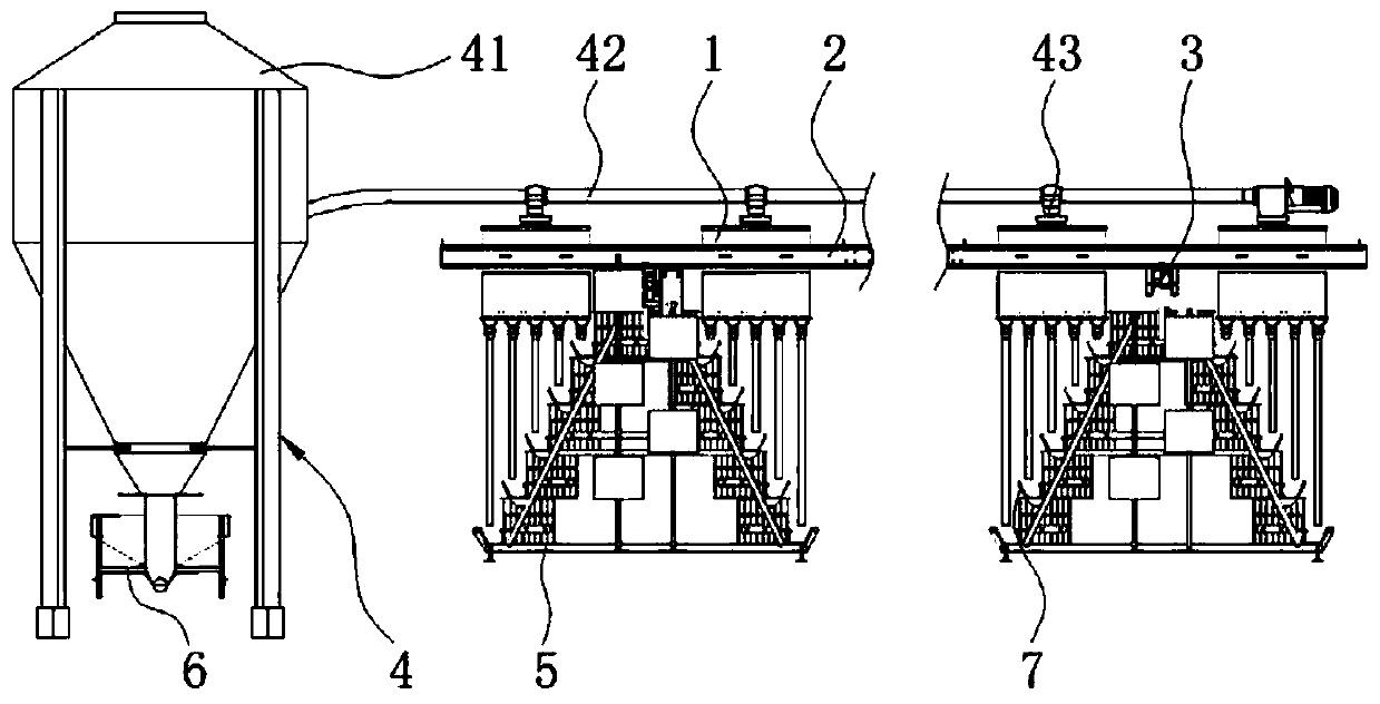
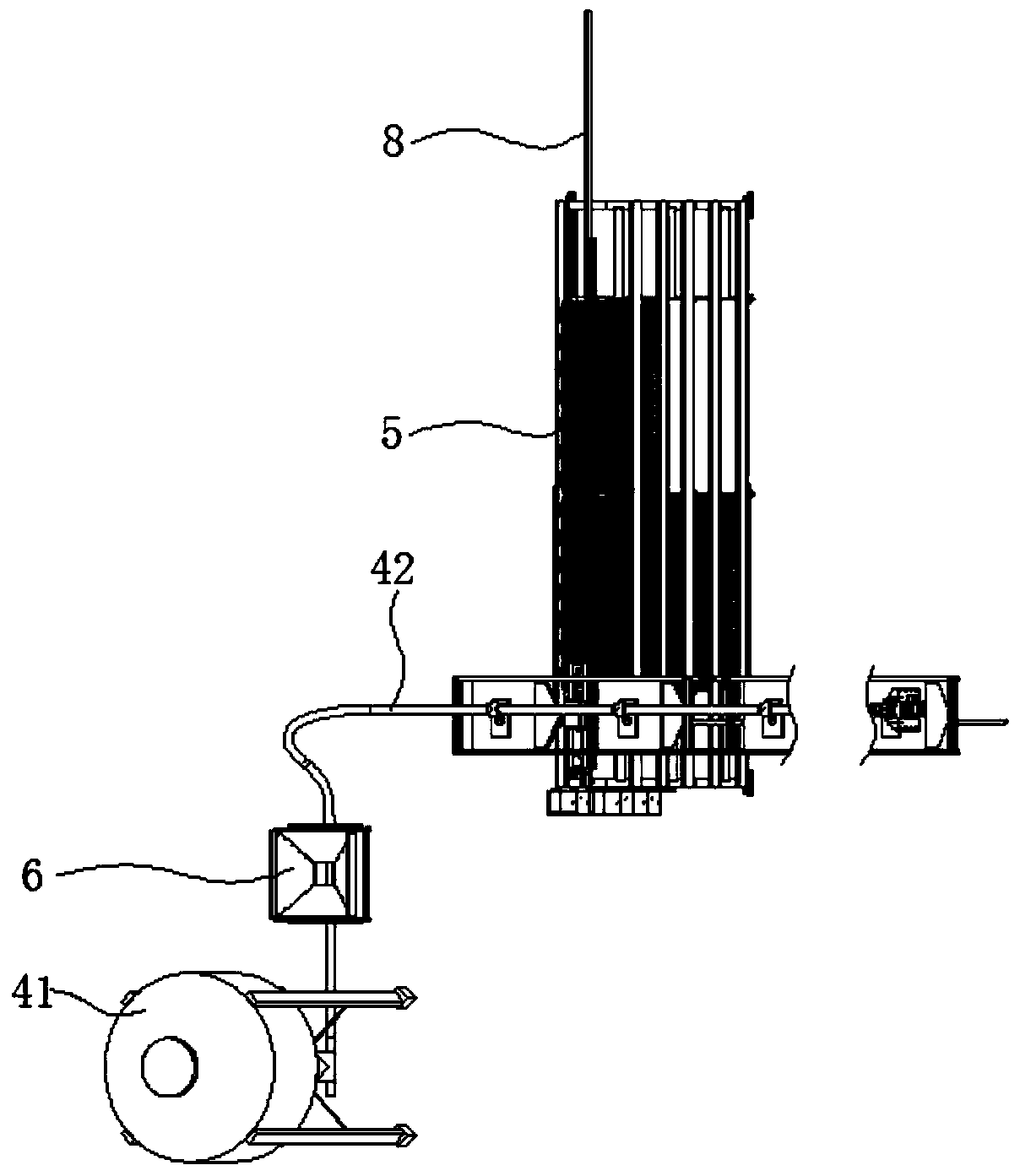
[0027] like Figure 1-4 As shown, a kind of automated chicken raising equipment of the preferred embodiment of the embodiment of the present invention includes a feeding mechanism 4, a chicken cage frame 5 and a feeding device arranged on the chicken cage frame 5;

[0028] The feeding mechanism 4 includes a feed bin 41, and the outlet of the feed bin 41 is provided with a feed pipe 42, and the feed pipe 42 is provided with a distribution pipe 43 corresponding to the feeding equipment;

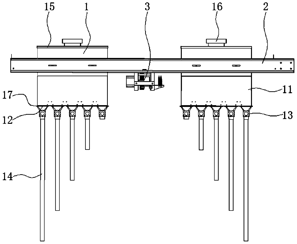
[0029] The feeding equipment includes two sets of feeding mechanisms 1, connecting frame 2 and mobile trolley 3 which are respectively arranged on both sides of the chicken cage frame 5, a...


PUM


Abstract

The invention relates to the technical field of poultry raising, and discloses automatic chicken raising equipment, which comprises a feeding mechanism, chicken cage frames and feeding devices; the feeding devices are arranged on the chicken cage frames; the feeding equipment comprise a feed bin, a feed lifting pipe is arranged at an outlet of the feed bin, and feed distributing pipes corresponding to the feeding devices are arranged on the feed lifting pipe; the feeding devices comprise two sets of feeding mechanisms respectively arranged on the both sides of the chicken cage frames, a connecting frame and a moving trolley, the two sets of feeding mechanisms are respectively connected at two ends of the connecting frame, and the moving trolley is arranged in the middle of the connecting frame and moves along the chicken cage frame; and feeding mechanisms comprise feed boxes, a plurality of discharging ports are formed in the lower ends of the feed boxes, a discharging mechanism is arranged at each discharging port, and the discharging mechanisms comprise shell bodies, spiral shafts and motors driving the spiral shafts to rotate, and the spiral shafts are arranged inside the shellbodies. The equipment can increase the number of chickens, control the feed amount of feed entering the feeding groove and ensure the use effect.

Description

technical field [0001] The invention relates to the technical field of poultry raising, in particular to an automatic chicken raising equipment. Background technique [0002] At present, large-scale chicken farms in China have realized automatic feeding, but at present, most of them adopt a single-row structure, and only one side of the trough can be set up, resulting in chicken cages occupying the space of the farm and reducing the number of chickens to be fed. . At the same time, the current feeding mechanism cannot accurately control the amount of feed put into the manger, resulting in waste of feed or the situation that the chickens are not full. In addition, most of the current mobile trolleys are straddled on the chicken cage frame, and the wheels drive directly on the ground. This not only takes up the passage space and makes it inconvenient for people to move, but also has the possibility of being unable to move forward when encountering obstacles on the ground, whi...

Claims


Application Information

Patent Timeline
Patent Type & Authority Applications(China)
IPC IPC(8): A01K31/00A01K39/012
CPCA01K31/002A01K39/0125
Inventor 姚远平曾全钟全如
Owner 清农集团有限公司
Why Eureka
Try Eureka