Automatic feeding and discharging machine
An automatic loading and unloading and feeding technology, which is applied to metal processing equipment, feeding devices, manufacturing tools, etc., can solve the problems of low efficiency of manual loading and unloading, and achieve the effects of convenient centralized collection, reduced errors, and flexible movement
- Summary
- Abstract
- Description
- Claims
- Application Information
AI Technical Summary
Problems solved by technology
Method used
Image
Examples
Embodiment 1
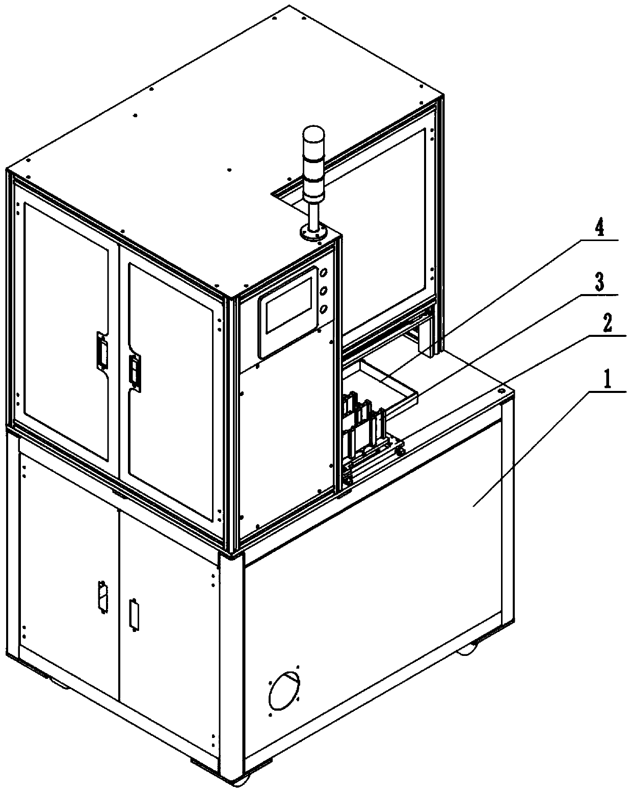
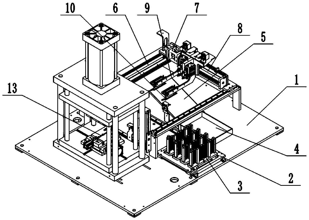
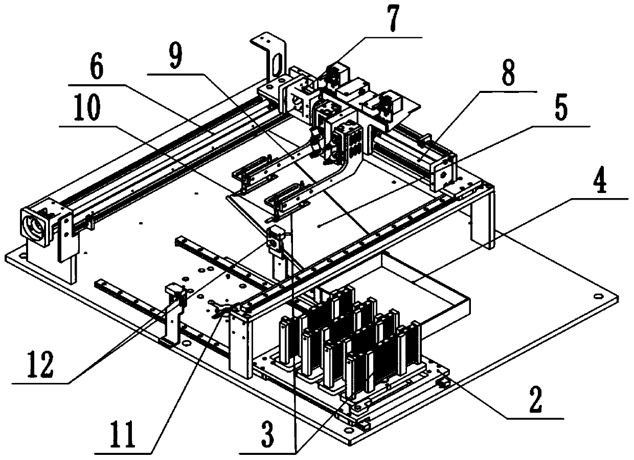
[0033] Such as figure 1 , figure 2 , image 3 As shown, the automatic loading and unloading machine includes an electric control cabinet 1. The upper end of the electric control cabinet 1 is provided with a feeding assembly, a retrieving assembly and a transmission assembly. The feeding assembly includes a carrier plate 2 that is slidably connected to the upper end of the electric control cabinet 1. There are a plurality of placement positions arranged on the plate 2 along its sliding direction. In this embodiment, there are four placement positions, and each placement position is fixed with a plurality of vertical clamping rods 13, and the workpiece 3 can be stuck in the placement position. Between the two clamping rods 13.
[0034] The lower end of each placement position is provided with a through groove, and the upper end of the electric control cabinet 1 is vertically slidably connected with a jacking piece. The jacking piece includes a jacking rod 11 and a cylinder fo...
Embodiment 2
[0043] The only difference between this embodiment and Embodiment 1 is that the settings of the retrieving arm 9 and the vacuum suction cup 10 in the retrieving assembly are different. Specifically, in combination with Figure 4 As shown, the lower end of the retrieving arm 9 is fixed with a piston barrel 15 with a lower end seal, the piston barrel 15 is vertically slidably connected with a piston 16, and the retrieving arm 9 is fixed with a driver 24 for driving the vertical sliding of the piston 16. Drive part 24 selects cylinder for use in the example, and the cylinder output shaft lower end and piston 16 upper surfaces are fixed. The lower end of the piston 16 is fixed with a connecting rod 17 , and the lower end of the connecting rod 17 runs through the piston barrel 15 and is fixed with the vacuum chuck 10 . A connection hole 21 is provided on the lower surface of the piston barrel 15 , and a pipeline is communicated between the connection hole 21 and the vacuum chuck 10...
PUM
 Abstract
Description
Claims
Application Information
 - R&D
- Intellectual Property
- Life Sciences
- Materials
- Tech Scout
- Unparalleled Data Quality
- Higher Quality Content
- 60% Fewer Hallucinations
Browse by: Latest US Patents, China's latest patents, Technical Efficacy Thesaurus, Application Domain, Technology Topic, Popular Technical Reports.
© 2025 PatSnap. All rights reserved.Legal|Privacy policy|Modern Slavery Act Transparency Statement|Sitemap|About US| Contact US: help@patsnap.com


