
Automatic loading and unloading machine

An automatic loading and unloading and feeding technology, which is applied to storage devices, metal processing equipment, feeding devices, etc., can solve the problems of low efficiency of manual loading and unloading, and achieve the effects of convenient centralized collection, improved processing efficiency, and flexible movement

Active Publication Date: 2020-12-25
重庆新固兴科技有限公司
View PDF5 Cites 0 Cited by
  • Summary
  • Abstract
  • Description
  • Claims
  • Application Information

AI Technical Summary

Problems solved by technology

[0004] Aiming at the deficiencies in the prior art, the present invention provides an automatic loading and unloading machine to solve the problem of low manual loading and unloading efficiency, thereby meeting the needs of automated production

Method used

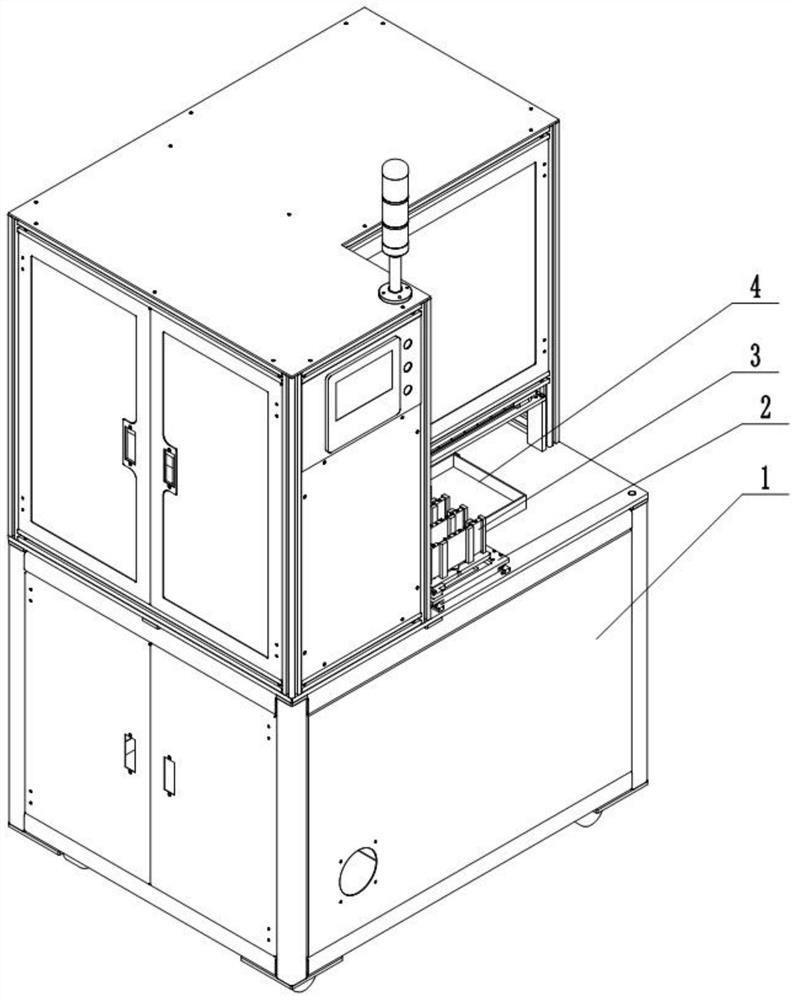
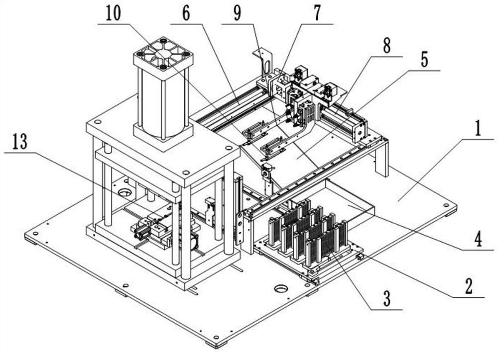
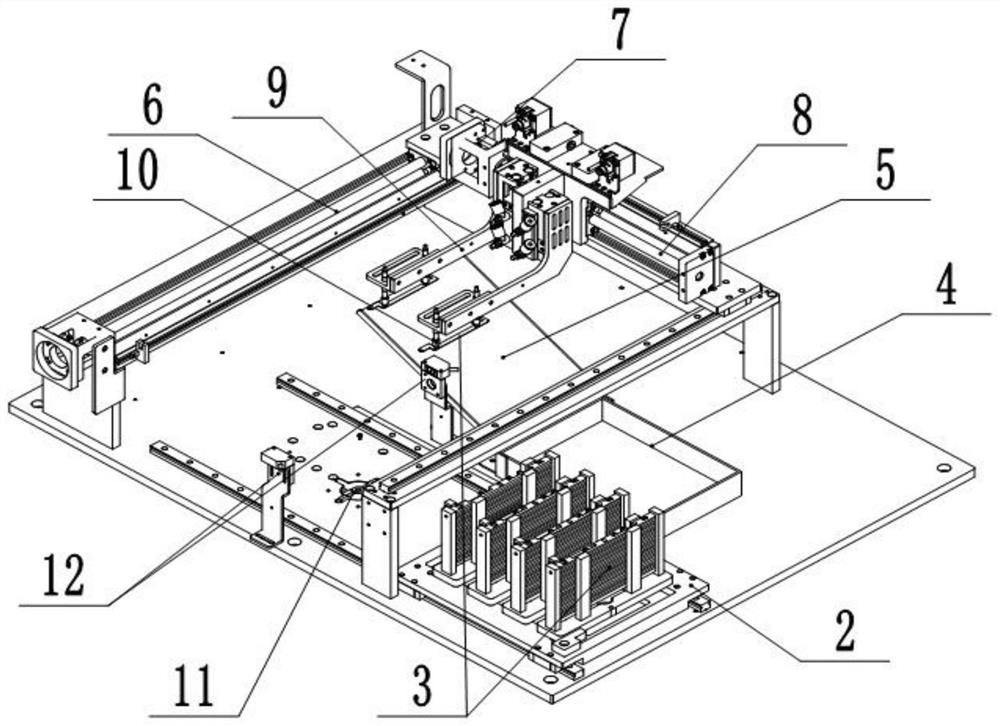

Image

  • Automatic loading and unloading machine
  • Automatic loading and unloading machine
  • Automatic loading and unloading machine

Examples


Embodiment 1

[0033] Such as figure 1 , figure 2 , image 3 As shown, the automatic loading and unloading machine includes an electric control cabinet 1. The upper end of the electric control cabinet 1 is provided with a feeding assembly, a retrieving assembly and a transmission assembly. The feeding assembly includes a carrier plate 2 that is slidably connected to the upper end of the electric control cabinet 1. There are a plurality of placement positions arranged on the plate 2 along its sliding direction. In this embodiment, there are four placement positions, and each placement position is fixed with a plurality of vertical clamping rods 13, and the workpiece 3 can be stuck in the placement position. Between the two clamping rods 13.

[0034] The lower end of each placement position is provided with a through groove, and the upper end of the electric control cabinet 1 is vertically slidably connected with a jacking piece. The jacking piece includes a jacking rod 11 and a cylinder fo...

Embodiment 2

[0043] The only difference between this embodiment and Embodiment 1 is that the settings of the retrieving arm 9 and the vacuum suction cup 10 in the retrieving assembly are different. Specifically, in combination with Figure 4 As shown, the lower end of the retrieving arm 9 is fixed with a piston barrel 15 with a lower end seal, the piston barrel 15 is vertically slidably connected with a piston 16, and the retrieving arm 9 is fixed with a driver 24 for driving the vertical sliding of the piston 16. Drive part 24 selects cylinder for use in the example, and the cylinder output shaft lower end and piston 16 upper surfaces are fixed. The lower end of the piston 16 is fixed with a connecting rod 17 , and the lower end of the connecting rod 17 runs through the piston barrel 15 and is fixed with the vacuum chuck 10 . A connection hole 21 is provided on the lower surface of the piston barrel 15 , and a pipeline is communicated between the connection hole 21 and the vacuum chuck 10...


PUM


Abstract

The invention relates to the field of mechanical automation, and particularly relates to an automatic feeding and discharging machine. The automatic feeding and discharging machine comprises a feedingassembly, a material taking assembly and a conveying assembly, wherein the feeding assembly comprises a carrying plate and a jacking piece; the carrying plate is provided with a plurality of containing positions used for containing workpieces; the jacking piece comprises ejector rods capable of being inserted into the containing positions; the material taking assembly comprises a material takingarm and a vacuum suction cup mounted at the lower end of the material taking arm and used for adsorbing the workpieces; the conveying assembly comprises a y-axis sliding rail and an x-axis sliding rail; the x-axis sliding rail and the y-axis sliding rail are perpendicular to each other; the y-axis sliding rail is in sliding connection with a sliding base; the x-axis sliding rail is arranged on thesliding base; and the material taking arm is in sliding connection to the x-axis sliding rail. By the adoption of the scheme, automatic feeding and discharging of the workpieces in the bending work can be achieved, and the machining efficiency is improved.

Description

technical field [0001] The invention relates to the field of mechanical automation, in particular to an automatic loading and unloading machine. Background technique [0002] Sheet metal is a comprehensive cold processing process for metal sheets (usually below 6mm), including shearing, punching, cutting, compounding, folding, welding, riveting, splicing, forming (such as automobile body) and other processes. Taking sheet metal bending as an example, sheet metal bending refers to the bending of sheet metal into the required shape under the pressure of the upper or lower die of the bending machine. [0003] Sheet metal bending requires the use of bending molds. When bending the existing bending molds, it is necessary to manually hold the sheet metal and put it into the bending mold, then bend it, and then manually fold the sheet metal into the bending mold. The metal parts are removed, and this operation has the following defects: 1. Since the processed workpieces are genera...

Claims


Application Information

Patent Timeline
Patent Type & Authority Patents(China)
IPC IPC(8): B21D43/18
CPCB21D43/18
Inventor 匡增波
Owner 重庆新固兴科技有限公司
Learn More