Slag flushing structure

A technology of flushing slag and flushing slag ditch, which is applied in the sewer pipeline system, building, water supply device, etc., can solve the problems of unsuitable construction and high construction cost of pedestrian platform, and achieve the effect of reducing construction cost and facilitating construction.

Pending Publication Date: 2020-02-28
MCC CAPITAL ENGINEERING & RESEARCH
View PDF0 Cites 2 Cited by
  • Summary
  • Abstract
  • Description
  • Claims
  • Application Information

AI Technical Summary

Problems solved by technology

[0004] The purpose of the present invention is to provide a slag flushing structure, which can effectively solve the shortcomings of high cost and unsuitable construction of pedestrian platforms in the prior art

Method used


Image

  • Slag flushing structure
  • Slag flushing structure
  • Slag flushing structure

Examples


Embodiment Construction

[0038] In order to have a clearer understanding of the technical solutions, purposes and effects of the present invention, the specific embodiments of the present invention will now be described with reference to the accompanying drawings.

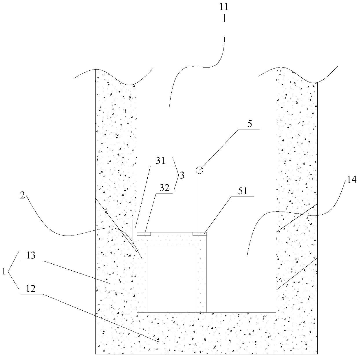
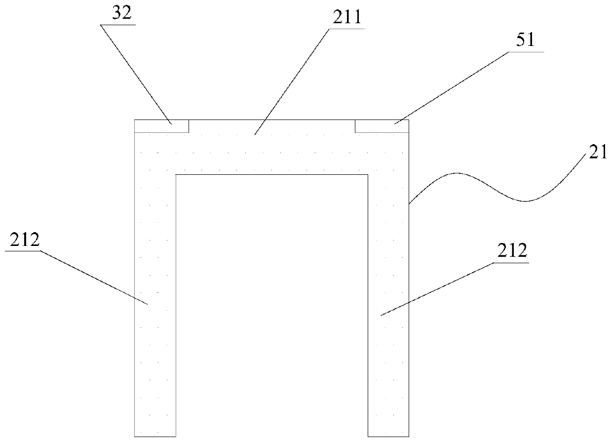
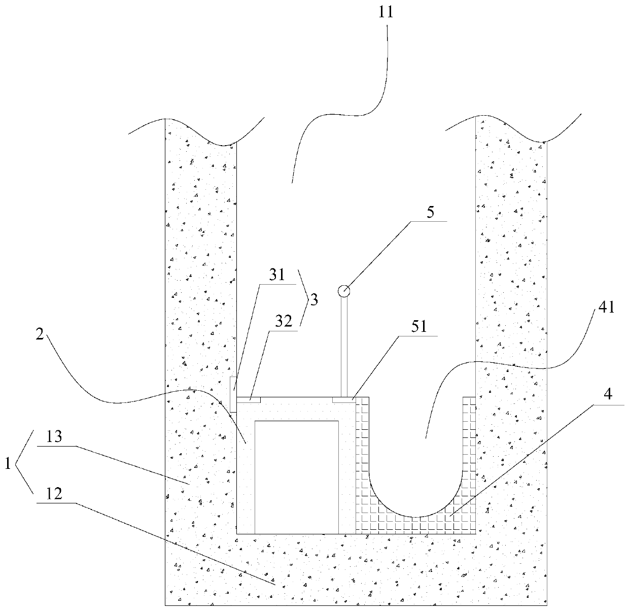
[0039] like figure 1 and image 3 As shown, the present invention provides a slag flushing structure, wherein the slag flushing structure includes a structural body 1 and a platform member 2, and a groove 11 with an open top is formed on the structural body 1, that is, the structural body 1 is provided with a concave groove 11. In the groove 11, the platform member 2 is installed at the bottom of the groove 11, and the platform member 2 extends along the length direction of the groove 11. The first side of the platform member 2 is disposed close to the inner wall of the first side of the groove 11. A ditch 14 is formed between the second side and the inner wall of the second side of the ditch 11 for the slag flushing water to pass through...


PUM


Abstract

The invention provides a slag flushing structure. The slag flushing structure comprises a structure body and a platform component, wherein a groove with an opening in the top is formed in the structure body; the platform component is mounted at the bottom of the groove; the platform component extends in the length direction of the groove; the first side of the platform component is arranged closeto the inner wall of the first side of the groove; a ditch is formed between the second side of the platform component and the inner wall of the second side of the groove; and the top surface of the platform component is horizontally arranged. According to the slag flushing structure, the prefabricated platform component is directly mounted in the groove of the structure body, reinforced concretepouring is not needed, and construction personnel do not need to carry out building block construction in a narrow space, so that the overall manufacturing cost of a pedestrian platform and the slag flushing structure are effectively reduced, and the slag flushing structure has the advantage of being convenient to construct; and meanwhile, the platform component is separated from the structure body, so that the stress analysis of all parts of the structure body by workers is facilitated.

Description

technical field [0001] The invention relates to a building structure in the metallurgical industry, in particular to a slag flushing structure. Background technique [0002] Slag flushing ditch is a common structure in metallurgical industry projects. The length ranges from tens of meters to hundreds of meters. It has a certain slope along the length. Some are located on the equipment platform on the ground, and most of them are located several meters to ten meters underground. . The slag flushing ditch uses slag flushing water as the carrier to flush the iron oxide scale produced in the smelting and rolling process into the iron scale sedimentation tank. The slag flushing ditch has a groove structure, a pedestrian platform is protruded from the bottom of the groove structure near one side of the groove wall, and a ditch for the slag flushing water to flow is formed between the pedestrian platform and the other side groove wall of the groove structure. [0003] In the curr...

Claims


Application Information

Patent Timeline
IPC IPC(8): E03F3/04C21B3/08C21B7/14
CPCC21B3/08C21B7/14C21B2400/024C21B2400/066E03F3/04
Inventor 刘兆强刘志侠荣哲毕成
Owner MCC CAPITAL ENGINEERING & RESEARCH
Why Eureka
Try Eureka