
A mechanical test device for sliding tube nut support fittings

A technology for mechanical testing and sliding tubes, which is used in the testing of mechanical parts, measuring devices, and testing of machine/structural parts, etc. It can solve the problem of inability to fully simulate the sliding tube parent support hardware, no mechanical testing device found, and high applicable occasions. problems, to achieve the effect of convenient mechanical test operation, easy operation and overall stability

Active Publication Date: 2017-02-22
STATE GRID CORP OF CHINA +1
View PDF5 Cites 0 Cited by
  • Summary
  • Abstract
  • Description
  • Claims
  • Application Information

AI Technical Summary

Problems solved by technology

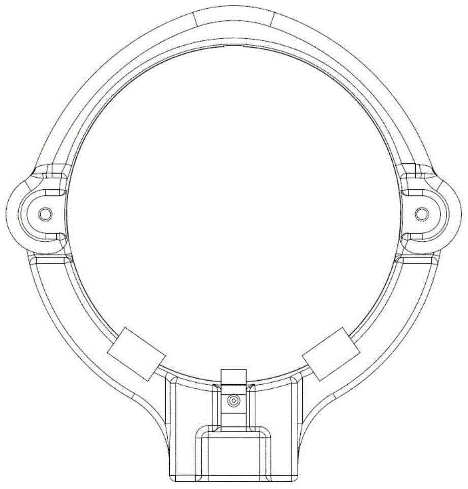
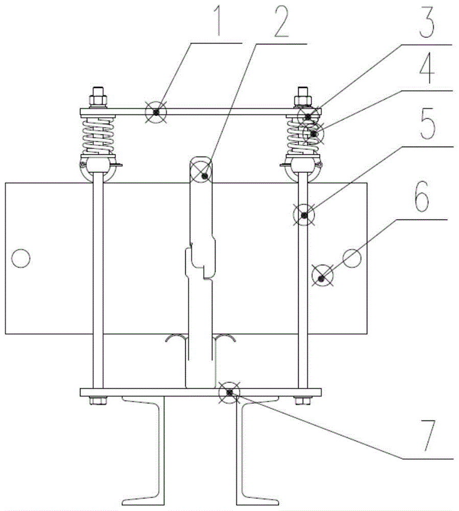
[0002] Fittings for ±800kV DC converter stations have only been used in China in recent years, and there is no corresponding national standard. Some type tests can only be carried out with reference to line fittings, such as figure 1 , 2 The sliding tube support fittings shown are used in conjunction with the tube tube in the converter station. At present, no mechanical test device similar to this application has been found in the prior art.
In addition, when performing mechanical tests on electric fittings, in order to simulate the on-site installation and use conditions, it is necessary to set up a test device close to the stress state during operation for the tested fittings. In the prior art, the number of weight plates is controlled to simulate the mechanical The load during the test has a complex structure, takes up a large space, and has high requirements for applicable occasions, and cannot fully simulate the actual operation of the sliding tube support fittings to complete the mechanical test of the sliding tube support fittings

Method used


Image

  • A mechanical test device for sliding tube nut support fittings
  • A mechanical test device for sliding tube nut support fittings
  • A mechanical test device for sliding tube nut support fittings

Examples


Embodiment Construction

[0025] Such as Figure 1-9 As shown, a mechanical test device for sliding pipe female supporting fittings includes a test base 7, and a mounting structure for sliding pipe female supporting fittings is arranged on the test base 7. The mounting structure can be a through hole or a mounting plate, and the sliding pipe The female supporting hardware is fixed on the above-mentioned test base 7 through the above-mentioned mounting structure. Two sets of pressure devices are also provided on both sides of the above-mentioned installation structure, and the two sets of pressure devices each include a supporting mechanism, a pressure spring 4, a tube nut pressure transmission member 8 and a limit device. The two sets of pressure devices are fixed on the test base 7 through the above-mentioned support mechanism. The above-mentioned support mechanism includes two screws 5 vertically fixed on the test base 7, and the two screws 5 corresponding to each set of pressure devices pass The thr...


PUM


Abstract

The invention discloses a mechanical testing device for sliding pipe bus support fittings. The mechanical testing device comprises a test pedestal on which an installation structure for the sliding pipe bus support fitting is arranged, wherein two sets of pressure devices are arranged on left and right sides of the installation structure; each set of pressure device comprises a support mechanism fixedly arranged on the test pedestal, a pressure spring arranged on the support mechanism, and a pipe bus pressure transmitting piece which is arranged on the support mechanism and pressures the auxiliary pipe bus, which is penetrated into the sliding pipe bus support fitting, under the effect of the pressure spring. The mechanical testing device can fully simulate the sliding pipe bus support fitting which is suffered from acting forces on two sides from the sliding pipe bus when in actual operation, is simple in structure and convenient to operate, and thereby the result of a mechanical test which verifies mechanical strength of the sliding pipe bus support fitting is more reliable.

Description

Technical field [0001] The invention relates to a mechanical test device for power fittings, in particular to a mechanical test device for a sliding pipe female supporting fittings. Background technique [0002] ±800kV DC converter station fittings have only been used in China in recent years, and there is no corresponding national standard. Some type tests can only be carried out with reference to line fittings, such as figure 1 , 2 The sliding pipe mother support fitting shown is used in conjunction with the pipe mother in the converter station. At present, no mechanical test device similar to this application has been found in the prior art. In order to simulate the on-site installation and use conditions of electric power fittings when performing mechanical tests, it is necessary to install a test device close to the force state of the tested fittings during operation. In the prior art, the number of weight plates is controlled to simulate electric power fittings machinery. T...

Claims


Application Information

Patent Timeline
Patent Type & Authority Patents(China)
IPC IPC(8): G01M13/00
Inventor 杨国华常林晶
Owner STATE GRID CORP OF CHINA
Learn More