
High-thrust welding spot strength shearing force testing device

A testing device and shear force technology, applied in the direction of using a stable shear force to test material strength, measuring device, strength characteristics, etc., can solve problems such as low life and poor accuracy

Pending Publication Date: 2021-09-14
深圳市德瑞茵精密科技有限公司
View PDF5 Cites 0 Cited by
  • Summary
  • Abstract
  • Description
  • Claims
  • Application Information

AI Technical Summary

Problems solved by technology

The existing shear force test module can no longer ensure a reliable force posture and reliable mechanical test results in the large-force shear test, and has poor accuracy and low life

Method used


Image

  • High-thrust welding spot strength shearing force testing device
  • High-thrust welding spot strength shearing force testing device
  • High-thrust welding spot strength shearing force testing device

Examples


Embodiment Construction

[0024] The following will clearly and completely describe the technical solutions in the embodiments of the present invention with reference to the accompanying drawings in the embodiments of the present invention. Obviously, the described embodiments are only part of the embodiments of the present invention, not all of them. Based on the embodiments of the present invention, all other embodiments obtained by persons of ordinary skill in the art without creative efforts fall within the protection scope of the present invention.

[0025] It should be noted that if there is a directional indication (such as up, down, left, right, front, back...) in the embodiment of the present invention, the directional indication is only used to explain the position in a certain posture (as shown in the accompanying drawing). If the specific posture changes, the directional indication will also change accordingly.

[0026] In addition, if there are descriptions involving "first", "second" and ...


PUM


Abstract

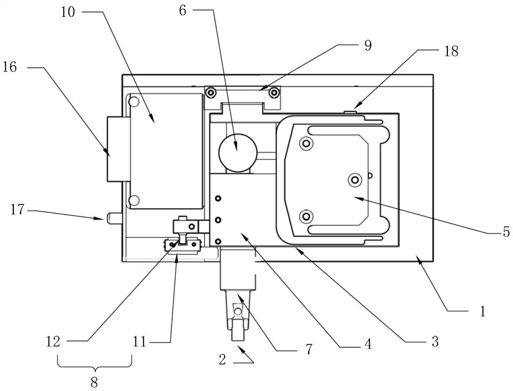
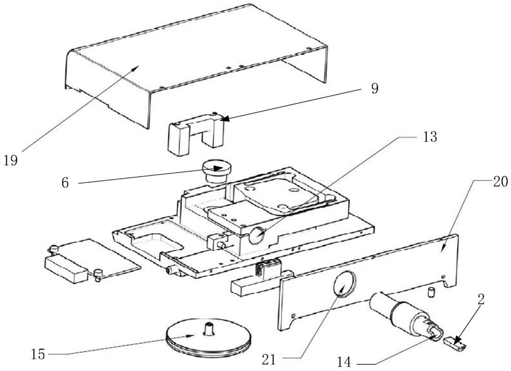
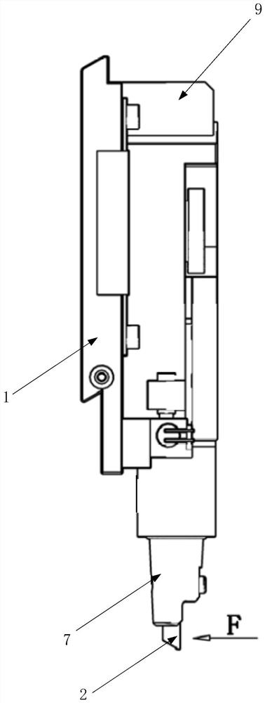
The invention discloses a high-thrust welding spot strength shearing force testing device. The device comprises a testing device bottom plate, a testing tool, a movable bracket, a pressing mechanism used for increasing the friction force of the movable end of the movable bracket relative to the testing device bottom plate, a force measuring sensor used for testing the shearing force, a displacement detection mechanism used for detecting the contact position of the testing tool, a blocking beam used for providing resistance moment for the movable end of the movable bracket, and a control circuit board, wherein the force measuring sensor and the displacement detection mechanism are respectively in signal connection with the control circuit board. According to the invention, a reliable stress posture and a reliable mechanical test result are ensured in a large-force shearing test, the detection precision is improved, the service life of the test device is prolonged, and the mechanical test measuring range is improved.

Description

technical field [0001] The invention relates to the technical field of high-thrust solder joint strength shear force testing, in particular to a high-thrust solder joint strength shear force test device. Background technique [0002] The shear test module is widely used in the shear test of various semiconductor device packaging, PCB assembly manufacturing or display COB manufacturing and other processes. With the gradual promotion of the manufacture of high-power devices, the strength requirements for the shear force test have been greatly increased. Usually, the shear test force of a solder joint used for an IBGT drive module of an electric train has exceeded 200KG. The solder joint of sintered silver technology, Its shear test strength has exceeded 400KG. The existing shear force test module can no longer ensure a reliable stress posture and reliable mechanical test results in a large-force shear test, and has poor precision and low life. Contents of the invention [...

Claims


Application Information

Patent Timeline
IPC IPC(8): G01N3/24G01N3/02
CPCG01N3/24G01N3/02G01N2203/0003G01N2203/0025G01N2203/005G01N2203/0091G01N2203/0296Y02E30/30
Inventor 唐声灿
Owner 深圳市德瑞茵精密科技有限公司
Learn More