
Loading device applied to drilling machines

A drilling rig and telescopic device technology, which is applied in the field of loading devices for drilling rigs, can solve problems such as high center of gravity, casualties, and vehicle overturning accidents, and achieve the effects of avoiding vehicle overturning accidents, high safety, and convenient operation

Pending Publication Date: 2020-02-28
徐州恒兴金桥地质装备有限公司
View PDF0 Cites 3 Cited by
  • Summary
  • Abstract
  • Description
  • Claims
  • Application Information

AI Technical Summary

Problems solved by technology

[0002] Crawler drilling rigs are suitable for geological drilling in various places, and often need to be transported between sites. Traditional construction machinery transport needs to build a ramp for the transition machinery to climb in the position of the transport vehicle compartment, and various The safety measures to prevent overturning during the transition mechanical climbing process are time-consuming and laborious, and various vehicle overturning accidents often occur, causing casualties and equipment damage. However, due to the high center of gravity of the vehicle, crawler drilling rigs are more likely to occur when using traditional methods to load and transfer Vehicle overturning accident, how to solve the above problems, it is necessary to provide a safe and efficient hydraulic lifting loading and unloading platform that can automatically load and unload crawler drilling rig equipment. The up and down movement of the legs realizes the automatic lifting of the crawler drilling rig and the cooperation of the transport vehicle to complete the automatic loading and unloading of loading and unloading

Method used


Image

  • Loading device applied to drilling machines
  • Loading device applied to drilling machines

Examples


Embodiment Construction

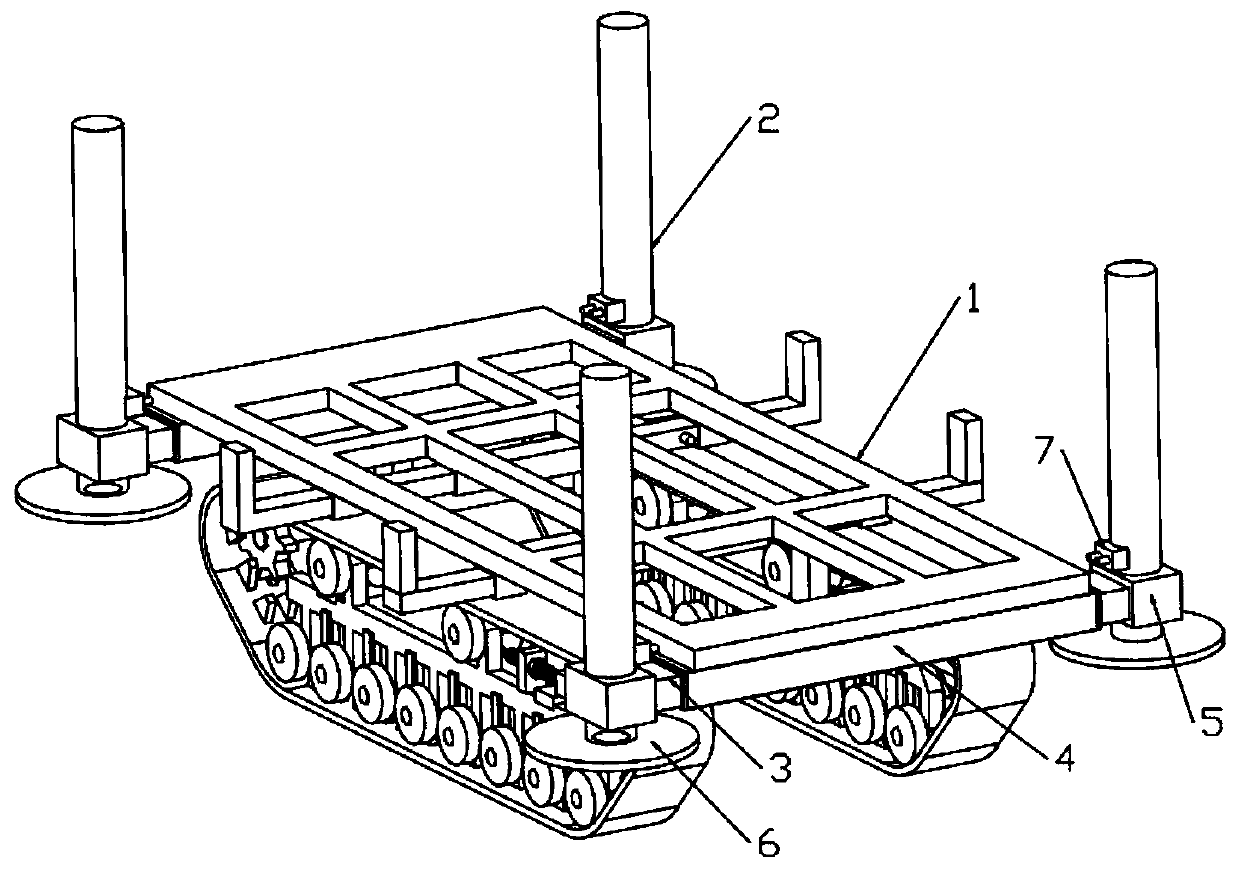
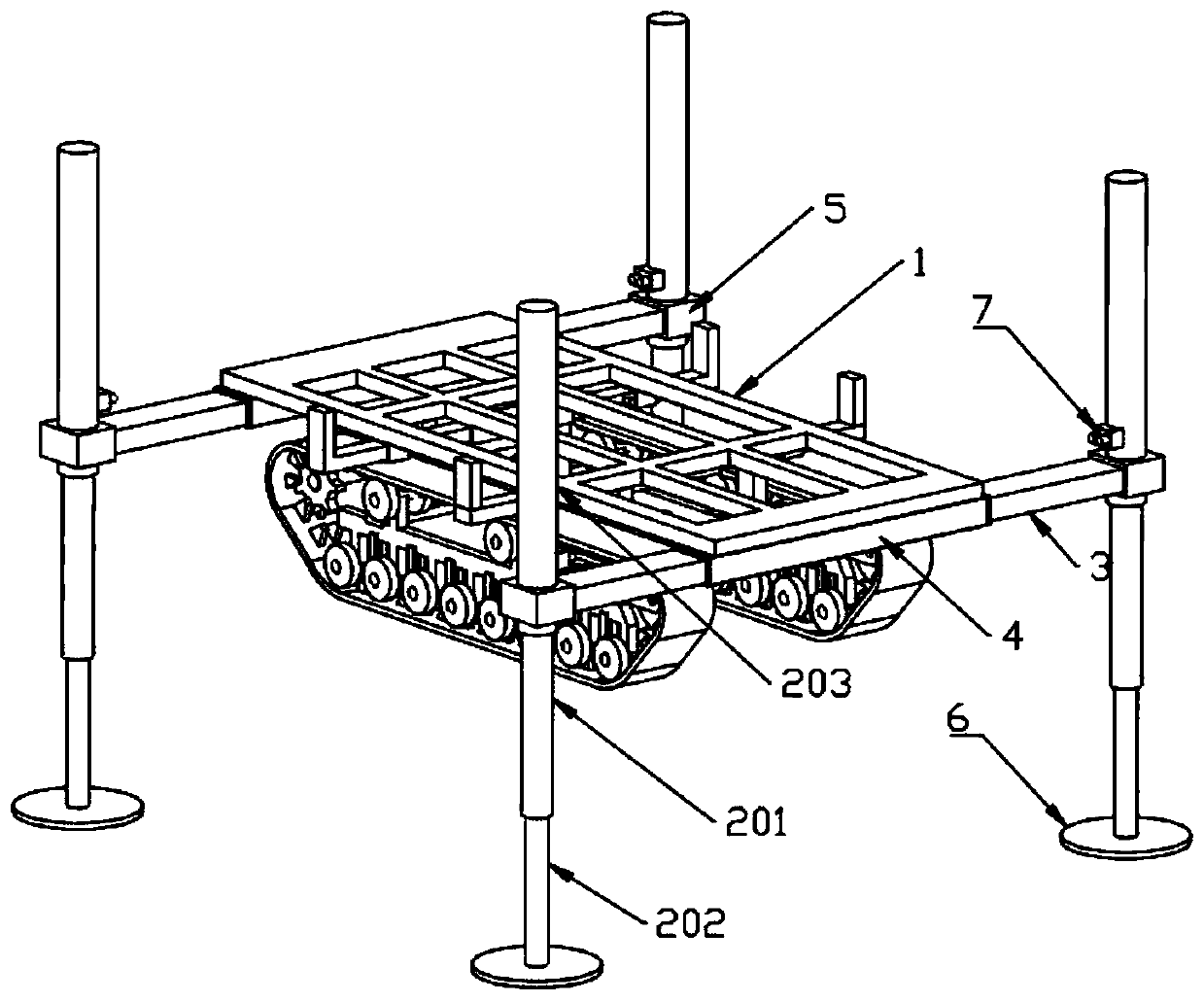
[0013] combined with figure 1 - attached figure 2 , a loading device for a drilling rig, comprising a chassis 1, a telescopic device 2, and a support arm 3 arranged below the drilling rig platform, the front and rear ends of the chassis 1 are fixedly provided with a chute 4, and one end of the support arm 3 is automatically The notch of the chute 4 extends into the inside of the chute 4, and the connecting block 5 provided at one end of the support arm 3 away from the chute is fixedly connected with the telescopic device 2, and the telescopic device 2 is provided with a telescopic rod inside, and the telescopic rod A spacer 6 is provided at the end.

[0014] As a preferred implementation of this embodiment, the telescopic device is composed of a first telescopic rod 201 , a second telescopic rod 202 and a hydraulic cylinder 203 which are sequentially socketed.

[0015] As a preferred implementation of this embodiment, the middle part of the connecting block 5 is provided wi...


PUM


Abstract

The invention relates to the field of engineering machines and particularly relates to a loading device applied to drilling machines. The loading device comprises a chassis, telescopic devices and support arms which are arranged under a drilling machine platform, wherein sliding grooves are fixedly arranged at the front end and the rear end of the chassis; one end of each support arm stretches into one sliding groove from a groove opening of the sliding groove; a connection block arranged at one end away from the sliding groove of each support arm is fixedly connected with one telescopic device; telescopic rods are arranged in each telescopic device; cushion blocks are arranged at the ends of the telescopic rods; the support arms are pulled out from the sliding grooves before using, then hydraulic modules are adjusted to control up-and-down motion of the telescopic rods in the telescopic devices, so that a crawler-type drilling machine is capable of automatically rising and falling andcooperates with a transportation vehicle to achieve automatic loading and unloading during loading and unloading.

Description

technical field [0001] The invention relates to the field of engineering machinery, in particular to a loading device for a drilling rig. Background technique [0002] Crawler drilling rigs are suitable for geological drilling in various places, and often need to be transported between sites. Traditional construction machinery transport needs to build a ramp for the transition machinery to climb in the position of the transport vehicle compartment, and various The safety measures to prevent overturning during the transition mechanical climbing process are time-consuming and laborious, and various vehicle overturning accidents often occur, causing casualties and equipment damage. However, due to the high center of gravity of the vehicle, crawler drilling rigs are more likely to occur when using traditional methods to load and transfer Vehicle overturning accident, how to solve the above problems, it is necessary to provide a safe and efficient hydraulic lifting loading and un...

Claims


Application Information

Patent Timeline
IPC IPC(8): E21B7/02E21B15/00
CPCE21B7/02E21B15/00
Inventor 崔云龙武维康
Owner 徐州恒兴金桥地质装备有限公司
Learn More