Weather-resistant type heat transfer printing light-emitting sign

A technology of luminous marking and thermal transfer printing, which is applied to illuminated markings, instruments, display devices, etc., can solve the problems of pattern layer thickness and low transparency, achieve high transmittance, improve luminous brightness, and excellent transparency. Effect

Inactive Publication Date: 2020-02-28
刘兵
View PDF0 Cites 2 Cited by
  • Summary
  • Abstract
  • Description
  • Claims
  • Application Information

AI Technical Summary

Problems solved by technology

[0003] At present, the more common printing method of luminous signs is screen printing. T

Method used


Image

  • Weather-resistant type heat transfer printing light-emitting sign

Examples


Embodiment 1

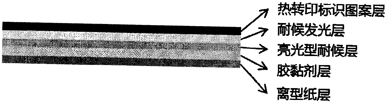
[0020] A weather-resistant heat-transfer luminescent sign, comprising a heat-transfer mark pattern layer, a weather-resistant luminous layer, a bright weather-resistant layer, an adhesive layer, and a release paper layer; one side of the bright weather-resistant layer is sequentially arranged from the inside to the outside It is a weather-resistant luminous layer and a thermal transfer logo pattern layer, and the other side is an adhesive layer and a release paper layer from the inside to the outside.

[0021] The thermal transfer logo pattern layer is printed with a thermal transfer ribbon using a thermal transfer method, and can be printed immediately according to actual needs. If it is necessary to print a red "No Smoking", a red ribbon is used to print it through thermal transfer printing. Method, the corresponding position of the printing head is heated, and the red "no smoking" that needs to be printed is printed on the formed tape (including the weather-resistant lumines...


PUM

PropertyMeasurementUnit
Angle of incidenceaaaaaaaaaa

Abstract

The invention provides a weather-resistant type heat transfer printing light-emitting sign. The sign comprises a heat transfer printing sign pattern layer, a weather-resistant light-emitting layer, alight type weather-resistant layer, an adhesive layer and a release paper layer, wherein the weather-resistant light-emitting layer and the heat transfer printing sign pattern layer are sequentially arranged on one side of the light type weather-resistant layer from inside to outside, and the adhesive layer and the release paper layer are sequentially arranged on the other side from inside to outside. The weather-resistant type heat transfer printing light-emitting sign is produced and printed by a heat transfer printing technology, so that completeness of the light-emitting layer is ensured,and the condition that the adding amount of efficient luminescent powder in materials is not damaged is maximally ensured; and compared with other printing modes such as screen printing, a pattern layer of the heat transfer printing sign is thinner and better in transparency, it can be ensured that light generated by the light-emitting layer has higher transmittance, luminance of the sign is effectively improved, and persistence of the sign is prolonged.

Description

technical field [0001] The invention belongs to the technical field of thermal transfer materials, in particular to a weather-resistant thermal transfer luminescent sign. Background technique [0002] The existing signs are very eye-catching during the day when the light is sufficient, and play a good role in warning. However, in nighttime operations, due to lack of light and reduced visual acuity, the signs are often unclear, and even some engineering vehicles cannot see the warning signs when passing through the cables, causing damage to cables and electrical equipment. In order to prevent safety accidents and man-made sabotage and power outages, it is particularly important to develop self-luminous signs to ensure that they can have a good warning function at night. [0003] At present, the more common printing method of luminous signs is screen printing, and the pattern layer printed by this printing method is thicker and the transparency is lower. Contents of the inv...

Claims


Application Information

Patent Timeline
IPC IPC(8): G09F13/20
CPCG09F13/20
Inventor 唐国初尹玉霞刘兵马敏
Owner 刘兵
Why Eureka
Try Eureka