Hollow bridge frame convenient to install and adjust

A technology of installation and adjustment, hollow bridge, applied in the direction of electrical components, etc., can solve the problems of low efficiency and labor consumption, and achieve the effect of ensuring mutual isolation, good heat dissipation effect, and enhancing practicability

Active Publication Date: 2020-02-28
ANHUI AUTOMATION INSTR
View PDF10 Cites 0 Cited by
  • Summary
  • Abstract
  • Description
  • Claims
  • Application Information

AI Technical Summary

Problems solved by technology

[0005] The purpose of the present invention is to solve the problems of labor-intensive and low efficiency in the prior art, and propose a hollow bridge that is easy to install and adjust.

Method used


Image

  • Hollow bridge frame convenient to install and adjust
  • Hollow bridge frame convenient to install and adjust
  • Hollow bridge frame convenient to install and adjust

Examples


Embodiment 1

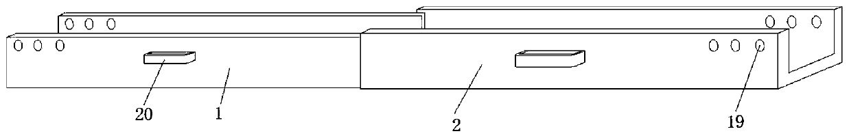
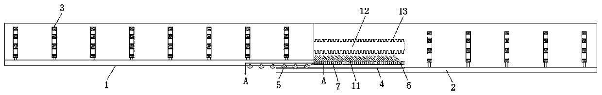
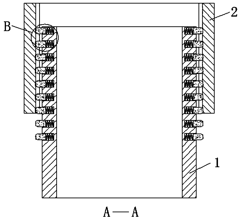
[0031] refer to Figure 1-7 , a hollow bridge frame that is easy to install and adjust, including bridge frame one 1 and bridge frame two 2, the inner bottom surfaces of bridge frame one 1 and bridge frame two 2 are fixed with branching devices 3, and the bottom surface of the bridge frame two 2 close to bridge frame one 1 is provided with rollers Groove 4, and the bottom surface of the side of bridge frame 1 near bridge frame 2 2 is equipped with ball 5, and ball 5 is placed in the rolling groove 4, and the inner wall of the front and rear ends of bridge frame 2 2 near the side of bridge frame 1 1 is provided with fixing groove 6, fixed The bottom surface of groove 6 is all provided with draw-in groove one 7, and bridge frame one 1 is all provided with groove 8 on the front and rear end outer wall near bridge frame two 2 sides, and the inwall of groove 8 is all slidably connected with card column 9, and card column 9 and Springs 10 are fixedly connected between the bottom sur...

Embodiment 2

[0034] like figure 1 and 7 As shown, this embodiment is basically the same as Embodiment 1. Preferably, a plurality of line distribution devices 3 are provided and distributed in a matrix on the inner bottom surface of the first bridge frame 1 and the second bridge frame 2. The line distribution device 3 includes a line distribution board 301 , and both sides of the distribution board 301 are provided with threading holes 302, and the lower end of the distribution board 301 is fixedly connected with a mounting block 303, and the mounting block 303 is fixed on the inner bottom surface of the first bridge frame 1 and the second bridge frame 2 by screws.

[0035] In this embodiment, a plurality of branching devices 3 are evenly fixed on the inner bottom surfaces of the first bridge frame 1 and the second bridge frame 2, so as to realize the reasonable arrangement of the cables, ensure that the cables are isolated from each other, and avoid the occurrence of slow heat dissipation ...

Embodiment 3

[0037] like figure 1 , 2, 5 and 7, the present embodiment is basically the same as Embodiment 1. Preferably, three threading holes 302 are provided and evenly distributed on the distribution board 301, and the diameter of the threading holes 302 gradually becomes smaller from top to bottom. A rubber pad 304 is also fixed on the inner wall of the hole 302 .

[0038] In this embodiment, the diameter of the threading hole 302 is gradually reduced from top to bottom, so that the lighter cable is placed on the upper end, so that the heat dissipation effect of the cable in the bridge frame is better, and a rubber pad 304 is fixed on the inner wall of the threading hole 302, which is very good Avoid that the cable will not be scratched by the inner wall of the threading hole 302.


PUM


Abstract

The invention discloses a hollow bridge frame convenient to install and adjust. The E hollow bridge frame comprises a bridge frame 1 and a bridge frame 2. A line-dividing device is fixed on the innerbottom surface of the bridge frame 1 and the bridge frame 2. A rolling groove is arranged on the bottom surface of one side of the bridge frame 2 near the bridge frame 1, and a rolling ball is installed on the bottom surface of one side of the bridge frame 1 near the bridge frame 2. The rolling ball is placed in the rolling groove. Fixing grooves are arranged on the inner walls of the front and rear ends of one side of the bridge frame 2 near the bridge frame 1. The bottom surfaces of the fixing grooves are provided with a clamping groove 1 respectively. The outer walls of the front and rearends of the bridge frame 1 close to the bridge frame 2 are provided with grooves. Clamping columns are slidably connected on the inner walls of the grooves. Springs are fixedly connected between the clamping columns and the bottom surfaces of the grooves, and the clamping columns are clamped and fixed in the clamping grooves 1. The inner top surfaces of the fixing grooves are also provided with circular arc grooves. The bridge frame has good adjustability and can realize flexible adjustment of length and angle is convenient to fix after adjustment and greatly reduces labor cost.

Description

technical field [0001] The invention relates to the technical field of automobile bridges, in particular to a hollow bridge that is easy to install and adjust. Background technique [0002] The hollow bridge is used to lay cables and protect the cables. Most of the cable bridges are fixed structures. During the installation process, the length of the joint needs to be cut, and the connection between the two hollow bridges is fixed by bolts. After cutting, it is necessary to Re-drilling holes at the connection is inefficient for installation. [0003] After retrieval, the patent application publication number 201821545568.1 discloses an adjustable cable bridge mechanism, which includes a bridge installed under the top beam, an adjustment component is provided between the top beam and the bridge, and slide rails are provided on both sides of the bridge. A slide seat is installed movable, and an n-shaped installation chute is provided on the upper part of one side of the slide...

Claims


Application Information

Patent Timeline
Patent Type & Authority Applications(China)
IPC IPC(8): H02G3/04H02G3/03
CPCH02G3/03H02G3/045
Inventor 柯正伟柯正涛
Owner ANHUI AUTOMATION INSTR
Why Eureka
Try Eureka