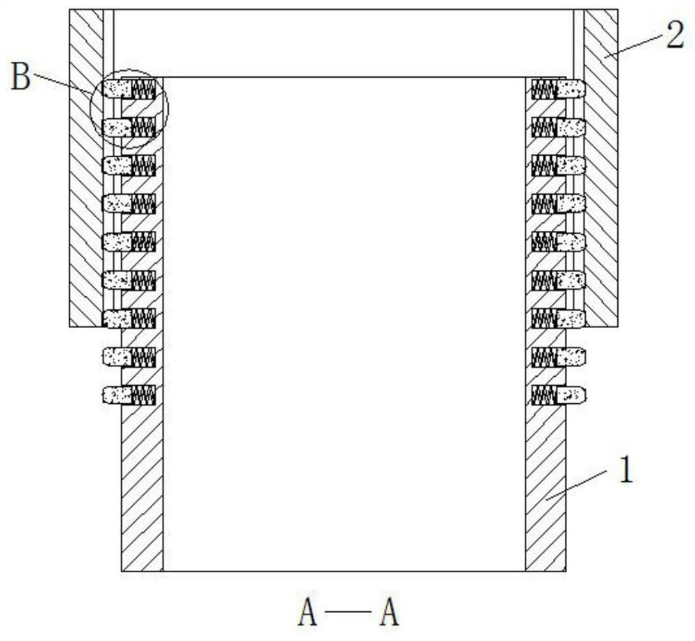
A hollow bridge frame that is easy to install and adjust
A technology of installation adjustment and hollow bridge, which is applied in the direction of electrical components, etc., can solve the problems of low efficiency and manpower consumption, and achieve the effect of ensuring mutual isolation, good heat dissipation effect, and guaranteed service life
- Summary
- Abstract
- Description
- Claims
- Application Information
AI Technical Summary
Problems solved by technology
Method used
Image
Examples
Embodiment 1
[0031] refer to Figure 1-7 , a hollow bridge frame that is easy to install and adjust, including bridge frame one 1 and bridge frame two 2, the inner bottom surfaces of bridge frame one 1 and bridge frame two 2 are fixed with branching devices 3, and the bottom surface of the bridge frame two 2 close to bridge frame one 1 is provided with rollers Groove 4, and the bottom surface of the side of bridge frame 1 near bridge frame 2 2 is equipped with ball 5, and ball 5 is placed in the rolling groove 4, and the inner wall of the front and rear ends of bridge frame 2 2 near the side of bridge frame 1 1 is provided with fixing groove 6, fixed The bottom surface of groove 6 is all provided with draw-in groove one 7, and bridge frame one 1 is all provided with groove 8 on the front and rear end outer wall near bridge frame two 2 sides, and the inwall of groove 8 is all slidably connected with card column 9, and card column 9 and Springs 10 are fixedly connected between the bottom sur...
Embodiment 2
[0034] Such as figure 1 and 7 As shown, this embodiment is basically the same as Embodiment 1. Preferably, a plurality of line distribution devices 3 are provided and distributed in a matrix on the inner bottom surface of the first bridge frame 1 and the second bridge frame 2. The line distribution device 3 includes a line distribution board 301 , and both sides of the distribution board 301 are provided with threading holes 302, and the lower end of the distribution board 301 is fixedly connected with a mounting block 303, and the mounting block 303 is fixed on the inner bottom surface of the first bridge frame 1 and the second bridge frame 2 by screws.
[0035] In this embodiment, a plurality of branching devices 3 are evenly fixed on the inner bottom surfaces of the first bridge frame 1 and the second bridge frame 2, so as to realize the reasonable arrangement of the cables, ensure that the cables are isolated from each other, and avoid the occurrence of slow heat dissipati...
Embodiment 3
[0037] Such as figure 1 , 2, 5 and 7, the present embodiment is basically the same as Embodiment 1, preferably, three threading holes 302 are provided and evenly distributed on the distribution board 301, and the diameter of the threading holes 302 gradually increases from top to bottom, and the threading holes A rubber pad 304 is also fixed on the inner wall of the hole 302 .
[0038] In this embodiment, the diameter of the threading hole 302 is gradually reduced from top to bottom, so that the lighter cable is placed on the upper end, so that the heat dissipation effect of the cable in the bridge frame is better, and a rubber pad 304 is fixed on the inner wall of the threading hole 302, which is very good Avoid that the cable will not be scratched by the inner wall of the threading hole 302.
PUM
 Abstract
Description
Claims
Application Information
 - R&D
- Intellectual Property
- Life Sciences
- Materials
- Tech Scout
- Unparalleled Data Quality
- Higher Quality Content
- 60% Fewer Hallucinations
Browse by: Latest US Patents, China's latest patents, Technical Efficacy Thesaurus, Application Domain, Technology Topic, Popular Technical Reports.
© 2025 PatSnap. All rights reserved.Legal|Privacy policy|Modern Slavery Act Transparency Statement|Sitemap|About US| Contact US: help@patsnap.com


