A double eccentric tip

A double eccentric, top technology, applied in the direction of tailstock/top, toolholder accessories, metal processing equipment, etc., can solve the problems of long adjustment time and low processing efficiency, so as to improve efficiency, improve processing efficiency, avoid Effect of Angle Offset

Active Publication Date: 2020-08-07
CHONGQING HONGGANG CNC MACHINE TOOL
View PDF6 Cites 0 Cited by
  • Summary
  • Abstract
  • Description
  • Claims
  • Application Information

AI Technical Summary

Problems solved by technology

[0005] The present invention intends to provide a double eccentric center to solve the problem of using the existing center, which takes a long time to adjust and leads to low processing efficiency

Method used


Image

  • A double eccentric tip
  • A double eccentric tip
  • A double eccentric tip

Examples


Embodiment 1

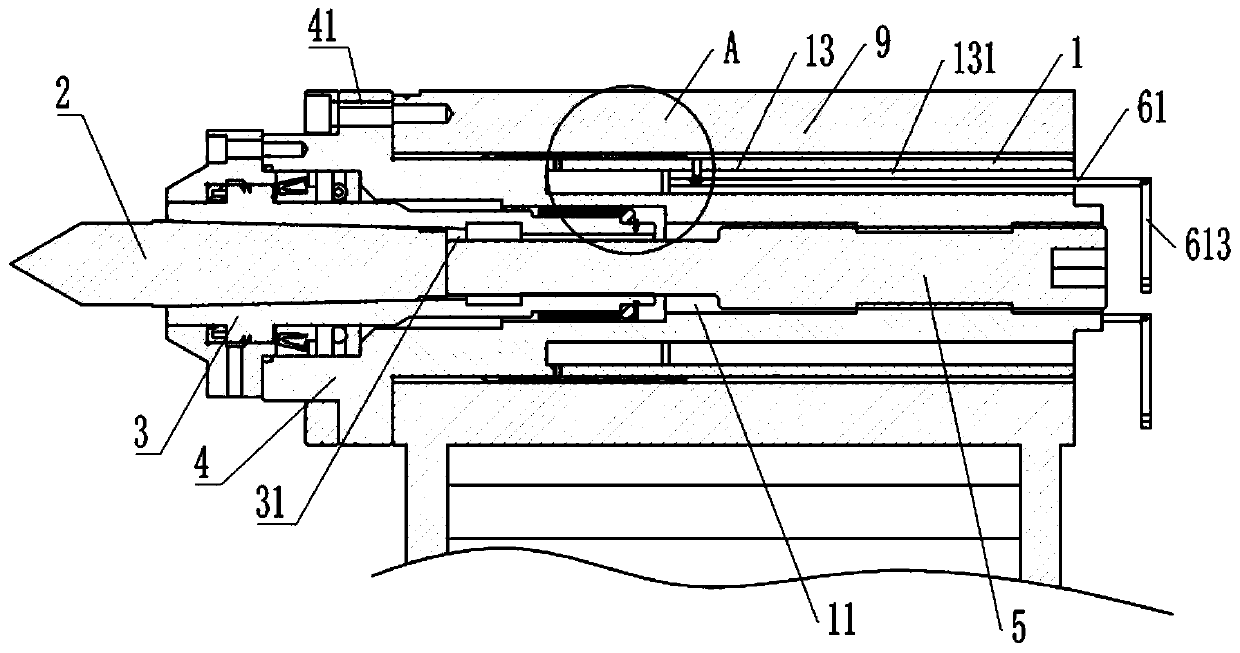
[0036] A double eccentric top, basically as attached figure 1 As shown, it includes a sleeve 1, a thimble 2, a mandrel 3 and a push rod 5. A connection plate 4 is provided on the outer wall of the left part of the sleeve 1, and three arc-shaped mounting holes 41 are provided on the connection plate 4 along the circumference. The sleeve 1 is provided with an eccentric hole 11, the eccentric hole 11 is a stepped hole, the mandrel 3 is installed on the left end of the eccentric hole 11, and the left end of the mandrel 3 protrudes from the left end of the eccentric hole 11; the eccentric hole 11 is located between the sleeve 1 and the core Two sets of bearings are arranged between the shafts 3, and the two sets of bearings are respectively located at the left and right ends of the mandrel 3. A sealing cover is installed on the part of the left end of the mandrel 3 outside the eccentric hole 11, and the right end of the sealing cover is against the left end of the sleeve 1; a rotar...

Embodiment 2

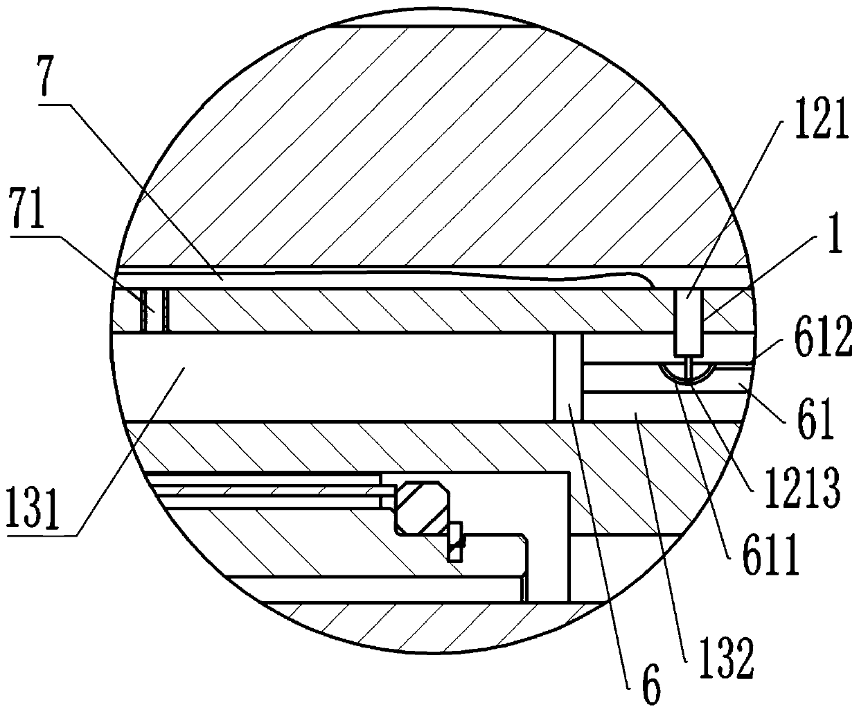
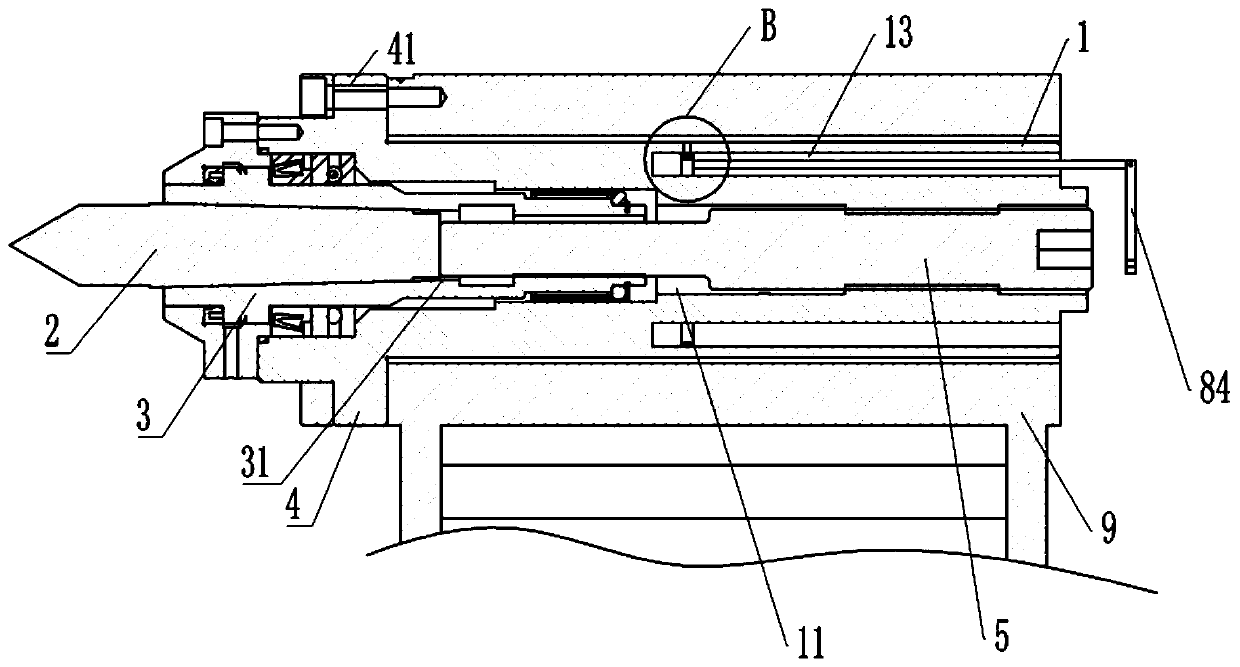
[0044] The difference between this embodiment and embodiment 1 is only that, as image 3 , Figure 4 As shown, the driving member includes an annular groove 13 arranged on the sleeve 1 and coaxial with the sleeve 1 , and the annular groove 13 is located on the outer ring of the eccentric hole 11 . The annular groove 13 communicates with the sliding groove 12, and the rotating ring 8 is connected in the annular groove 13, and the outer wall of the rotating ring 8 is provided with three placing grooves 81, and the outer wall of the rotating ring 8 is provided with an annular moving groove 82, and the moving groove 82 It is a T-shaped slot, and the moving slot 82 covers the placing slot 81 . The inner end of the positioning rod 121 is provided with a T-shaped block 1213 , and the T-shaped block 1213 is located in the moving groove 82 at the placement groove 81 , and the T-shaped block 1213 is slidably connected in the moving groove 82 . The right end surface of the rotating rin...

Embodiment 3

[0048] The only difference between this embodiment and embodiment 1 or embodiment 2 is that, as Figure 5 As shown, the positioning rod 121 includes a pressing part 1211 and a pushing part 1212, the pushing part 1212 is connected with the T-shaped block 1213, the bottom of the pressing part 1211 is provided with a sliding hole, and the top of the pushing part 1212 is vertically slidably connected in the sliding hole, and A spring is disposed between the pushing portion 1212 and the sliding hole. Sliding can occur between the positioning part 132 and the pushing part 1212, and a spring is provided between the two, so when the pressing part 1211 is worn for a long time, the tailstock 9 can also be continuously pressed against the tailstock 9 under the action of the spring .


PUM


Abstract

The present invention belongs to the technical field of a center for a tailstock of a machine tool, and discloses a double-eccentric tip, and the double-eccentric tip includes a sleeve, a thimble anda mandrel; the sleeve is provided with an eccentric hole; the mandrel is arranged in the eccentric hole of the front end; a bearing is positioned between the mandrel and the sleeve; a tapered hole isarranged in the mandrel, and the thimble is arranged in the tapered hole and matches with the taper of the tapered hole; the rear end of the sleeve is in threaded connection with an ejector pin against the thimble; the outer wall of the front end of the sleeve is provided with a connection disk on which a plurality of arc-shaped mounting holes are circumferentially arranged; and the middle part ofthe sleeve is provided with a compensation mechanism for overcoming the gap between the sleeve and the tailstock. The present invention solves the problem that the existing tip has the low processingefficiency due to long adjustment time consumption.

Description

technical field [0001] The invention belongs to the technical field of tips for machine tool tailstocks, and in particular relates to a double eccentric tip. Background technique [0002] The top is an auxiliary tool of the machine tool. It usually includes a sleeve, a thimble located in the sleeve, a mandrel that pushes the thimble to move, and a fixed pin for fixing the mandrel. The tail of the thimble fits with the taper of the mandrel. When in use, the apex is assembled on the tailstock of the machine bed, and the centering of the abutment against the workpiece is realized by sliding the tailstock. However, after the tip is used for a long time, the taper of the tip will change. In order to ensure the accuracy of use, the taper of the tip needs to be readjusted, and the way of adjusting the taper is realized by adjusting the distance between the machine bed and the tailstock . And this adjustment method can only rely on the experience of the workers, can not guarantee ...

Claims


Application Information

Patent Timeline
Patent Type & Authority Patents(China)
IPC IPC(8): B23B23/04
CPCB23B23/04
Inventor 汪传宏汪博强
Owner CHONGQING HONGGANG CNC MACHINE TOOL
Why Eureka
Try Eureka