
An automatic rolling device for continuous plate changing and cutting

A rolling device and automatic technology, which is applied in the cutting of textile materials, textiles and papermaking, metal processing, etc., can solve the problems of fabric deviation and wrinkling, the inability to take out the fabric, and potential safety hazards, so as to ensure the accuracy and improve the cutting efficiency of the fabric. Effect

Active Publication Date: 2021-11-19
宁波瑞利时数控科技有限公司
View PDF0 Cites 0 Cited by
  • Summary
  • Abstract
  • Description
  • Claims
  • Application Information

AI Technical Summary

Problems solved by technology

[0002] At present, when the existing cutting machine cuts the cloth, the cloth is moved to the conveyor belt of the cutting machine, and the cutting head on the cutting machine cuts the cloth into different formats. After cutting, the formed cloth of different formats and the remaining material It is also located on the conveyor belt, so the cut and shaped fabric is taken out manually. However, because the fabric is relatively attached to the conveyor belt when it is cut, there is no attachment point when it is manually taken out, and the cut and shaped fabric cannot be quickly taken out manually. , and when taking out, because the cutting head is cutting continuously, there is a certain potential safety hazard. At the same time, in the process of manual taking out, because the subsequent cloth is conveyed as a whole, when taking out the cloth manually, it is easy to cause it to be placed on the conveyor belt. The fabric in the uncut part of the fabric is offset and wrinkled, which affects the accuracy of the subsequent fabric cutting position

Method used


Image

  • An automatic rolling device for continuous plate changing and cutting
  • An automatic rolling device for continuous plate changing and cutting
  • An automatic rolling device for continuous plate changing and cutting

Examples


Embodiment Construction

[0024] The following will clearly and completely describe the technical solutions in the embodiments of the present invention with reference to the accompanying drawings in the embodiments of the present invention. Obviously, the described embodiments are only some, not all, embodiments of the present invention. Based on the embodiments of the present invention, all other embodiments obtained by persons of ordinary skill in the art without making creative efforts belong to the protection scope of the present invention.

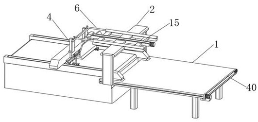
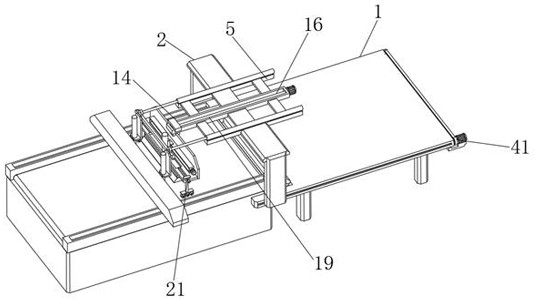
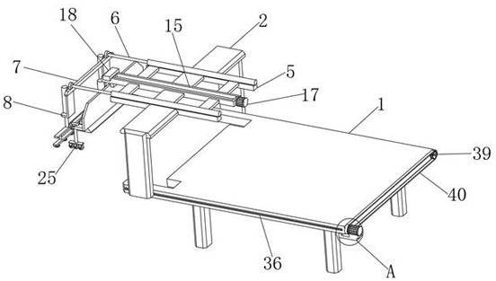
[0025] see Figure 1-8 , the present invention provides a technical solution: an automatic rolling device for continuous plate-changing cutting, including a discharge table 1, and a roller 35 can be added to the bottom of the discharge table 1, so as to facilitate the movement of the discharge table 1, Simultaneously, in order to guarantee the stable supporting effect of the discharging platform 1, reinforcing ribs are provided on the supporting legs at the bo...


PUM


Abstract

The invention discloses an automatic rolling device for continuous plate-changing cutting, which comprises a feeding table, the feeding table is located on the output end of a conveyor belt on a cloth cutting machine, a moving bracket is connected to the feeding table, and the moving The bottom of the bracket is provided with an adsorption plate for receiving the cloth cut by the cutting machine, and the two ends of the bottom of the adsorption plate are provided with a pressing device for pressing the edge of the cloth on the cutting machine, which is used for automatic plate-changing cutting. The rolling device and the adsorption plate connected to the suction table can realize the function of automatic feeding of the cloth of different formats after cutting, and at the same time of automatic feeding, and through the equipped pressing device, so as to play a role in the automatic feeding of the uncut cloth. The effect of pressing and separating the cloth at the cutting or cutting part is an effective way to cause the subsequent uncut cloth to shift when the cloth is taken out, ensuring the accuracy of the continuous plate-changing cutting of the cloth, and at the same time Improve cloth cutting efficiency.

Description

technical field [0001] The invention relates to the technical field of mechanical equipment, in particular to an automatic rolling device for continuous plate changing and cutting. Background technique [0002] At present, when the existing cutting machine cuts the cloth, the cloth is moved to the conveyor belt of the cutting machine, and the cutting head on the cutting machine cuts the cloth into different formats. After cutting, the formed cloth of different formats and the remaining material It is also located on the conveyor belt, so the cut and shaped fabric is taken out manually. However, because the fabric is relatively attached to the conveyor belt when it is cut, there is no attachment point when it is manually taken out, and the cut and shaped fabric cannot be quickly taken out manually. , and when taking out, because the cutting head is cutting continuously, there is a certain potential safety hazard. At the same time, in the process of manual taking out, because ...

Claims


Application Information

Patent Timeline
Patent Type & Authority Patents(China)
IPC IPC(8): B26D7/32B26D7/02D06H7/00
CPCB26D7/025B26D7/32B26D2007/0018D06H7/00
Inventor 吕森丰
Owner 宁波瑞利时数控科技有限公司
Learn More