Thermal-power ventilation device

A ventilation device and thermal power technology, applied in space heating and ventilation, ventilation systems, household heating, etc., can solve problems such as complex implementation, unsatisfactory effects, and waste of electric energy

Inactive Publication Date: 2020-03-06
易斯特林(广州)新能源科技发展有限公司
View PDF0 Cites 0 Cited by
  • Summary
  • Abstract
  • Description
  • Claims
  • Application Information

AI Technical Summary

Problems solved by technology

The natural ventilation method is more complicated to implement, and the effect is not ideal. The forced ventilation method requires additional power, and most of them need electricity to drive the fan to achieve ventilation and waste electric energy.

Method used


Image

  • Thermal-power ventilation device

Examples


Embodiment Construction

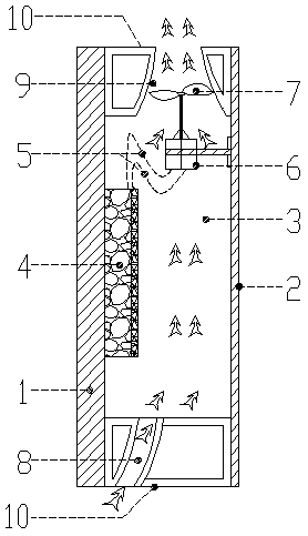
[0011] exist figure 1 Among them, one side of the heat conduction plate (1) faces the heat source, and the other side is connected to the hot end of the semiconductor generator (4). The heat conduction plate (1) transfers the collected heat to the semiconductor generator (4) to make it run to generate electricity. The wire (5) is transmitted to the motor (6), and the motor (6) runs to drive the fan (7) to rotate. Among them, the keel (10) and the back plate (2) are connected to each other to form a ventilation cavity (3), the ventilation port includes an air inlet (8) and an air outlet (9), and the fan (7) is set at the position of the air outlet (9). When the fan (7) The operation drives the air to flow out from the air outlet (9), and the air from the air inlet (8) is continuously replenished to realize air flow and achieve the ventilation effect.

[0012] The thermoelectric generator in this embodiment is illustrated by using a semiconductor thermoelectric generator as an ...


PUM


Abstract

The invention relates to a thermal-power ventilation device. By means of the thermal-power ventilation device, in combination with a thermoelectric generator, the thermoelectric generator can operateunder the temperature difference to drive a fan so as to achieve forced ventilation, thereby achieving a energy saving effect.

Description

technical field [0001] The invention relates to a ventilation device, in particular to a thermodynamic ventilation device. Background technique [0002] With the development of the construction industry, building energy consumption has attracted more and more attention from the industry. At present, reducing building energy consumption has become a key point that the industry must consider. Among them, ventilation is an effective way to reduce building energy consumption. At present, the commonly used method is to adopt natural ventilation or forced ventilation. The natural ventilation method is more complicated to implement, and the effect is not ideal. The forced ventilation method needs to provide additional power, and most of them need electricity to drive the fan to achieve ventilation and waste electric energy. If the thermal energy of the building surface can be utilized to generate electricity or power to achieve ventilation, the effect of forced ventilation can be...

Claims


Application Information

Patent Timeline
Patent Type & Authority Applications(China)
IPC IPC(8): F24F7/007
CPCF24F7/007
Inventor 胡海峰朱芝华其他发明人请求不公开姓名
Owner 易斯特林(广州)新能源科技发展有限公司
Why Eureka
Try Eureka