
Crankcase ventilation system of supercharger front pre-mixing gas engine and ventilation method of crankcase ventilation system

A technology for gas engine and crankcase ventilation, which is applied in the direction of crankcase ventilation, machine/engine, engine components, etc. It can solve the blockage of oil and gas separator, the pressure increase of engine crankcase, and can not fundamentally solve the safety of exhaust gas in the crankcase Emissions and other issues to achieve the effect of preventing oil emulsification and dew point reduction

Pending Publication Date: 2019-12-20
WEICHAI XIGANG NEW ENERGY POWER
View PDF0 Cites 12 Cited by
  • Summary
  • Abstract
  • Description
  • Claims
  • Application Information

AI Technical Summary

Problems solved by technology

However, the above method is less effective when the temperature of the engine operating environment is low. If the heat preservation effect is forced to be improved, it will be more likely to condense and freeze at the outlet of the oil-gas separator when the exhaust gas is mixed with air due to a sudden drop in temperature. , resulting in blockage of the oil-air separator, resulting in pressure rise in the engine crankcase, oil seal leakage and other failures
Therefore aforesaid method can not fundamentally solve the exhaust gas safety discharge problem in the crankcase

Method used


Image

  • Crankcase ventilation system of supercharger front pre-mixing gas engine and ventilation method of crankcase ventilation system
  • Crankcase ventilation system of supercharger front pre-mixing gas engine and ventilation method of crankcase ventilation system

Examples


Embodiment Construction

[0026] Below in conjunction with accompanying drawing and embodiment, further elaborate the present invention. In the following detailed description, certain exemplary embodiments of the invention are described by way of illustration only. Needless to say, those skilled in the art would realize that the described embodiments can be modified in various different ways, all without departing from the spirit and scope of the present invention. Accordingly, the drawings and description are illustrative in nature and not intended to limit the scope of the claims.

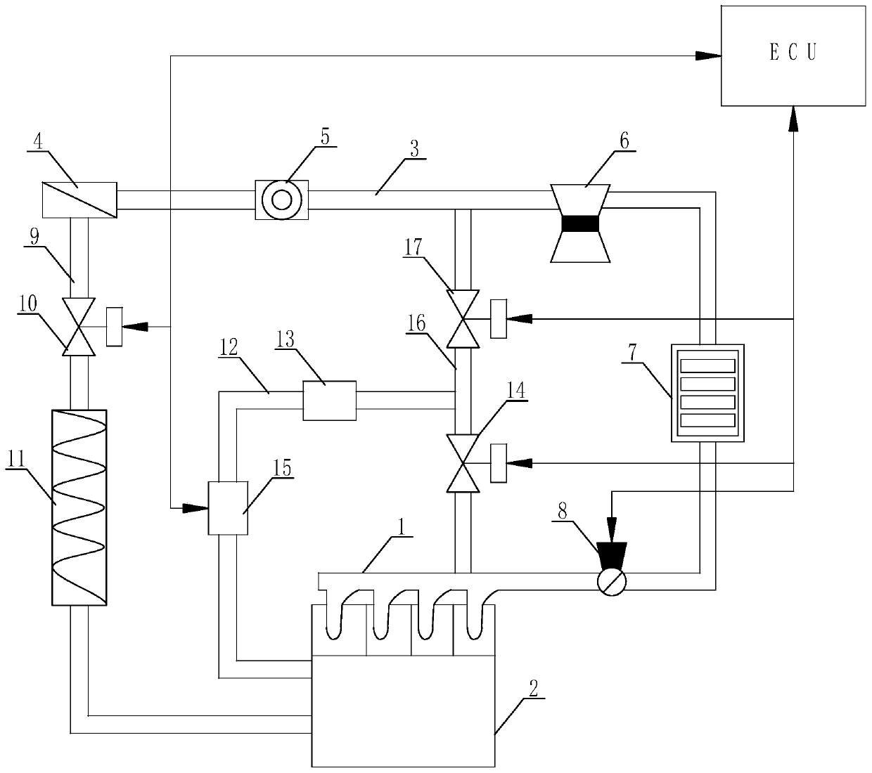
[0027] Such as figure 1 As shown, the crankcase ventilation system of the premixed gas engine before the supercharger is used in conjunction with the engine's electronic control unit ECU, including an intake manifold 1 and a crankcase 2 set on the engine, and the intake manifold 1 is connected to There is an intake pipe 3, on which an air filter 4, a mixer 5, a supercharger 6, an intercooler 7 and a throttle valve 8 are...


PUM


Abstract

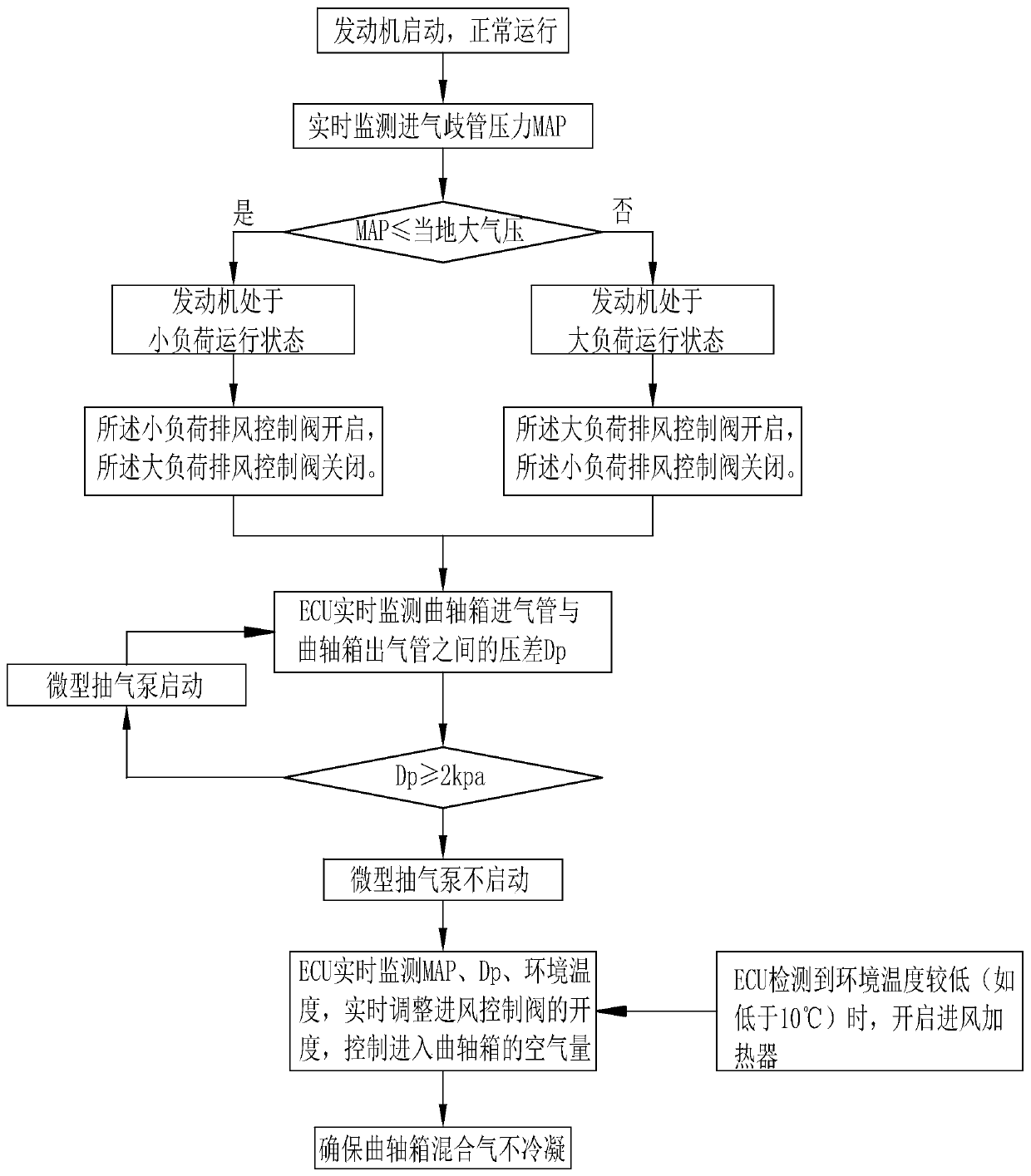
The invention discloses a crankcase ventilation system of a supercharger front pre-mixing gas engine. The crankcase ventilation system is used in cooperation with an ECU of the engine and comprises anair inlet branch pipe, a crankcase, an air inlet pipe, an air filter, a mixer, a supercharger, an intercooler and a throttle valve. The position between the air filter and the crankcase communicateswith an air inlet device, and the position between the crankcase and the air inlet branch pipe communicates with a small-load exhaust device. The small-load exhaust device is further connected with alarge-load exhaust device, and the large-load exhaust device and the air inlet branch pipe are arranged in parallel. The air outlet end of the large-load exhaust device is in communication with the part, between the mixer and the supercharger, of the air inlet pipe. A ventilation method of the system is further disclosed. Air is guided into the crankcase from a pipeline in front of the mixer, thecontent of moisture in the crankcase is reduced, accordingly, the dew point of the oil-gas mixer in the crankcase is reduced, the condensation phenomenon cannot happen, condensing and gathering of water steam into engine oil in an oil sump are eradicated, and it is ensured that damage of a lubricating component of the engine due to engine oil deterioration is avoided.

Description

technical field [0001] The invention relates to the technical field of engines, in particular to a crankcase ventilation system of a premixed gas engine before a supercharger, and also relates to a specific ventilation method of the system. Background technique [0002] When the engine is running, a part of the exhaust gas generated by combustion will escape into the crankcase through the piston ring. Exhaust gas contains water vapor and sulfur dioxide. If it is operated in a low-temperature environment, the water vapor in the crankcase will condense into water droplets when it flows to the breather, and it will easily flow into the oil pan. The mixture of liquid water and oil in the oil pan will cause the oil to emulsification. After the oil is emulsified, the ability to form an oil film in the friction mechanism will deteriorate, which will accelerate engine wear. When sulfur dioxide meets water, sulfurous acid will be produced, and sulfurous acid will form sulfuric acid...

Claims


Application Information

Patent Timeline
Patent Type & Authority Applications(China)
IPC IPC(8): F01M13/04F01M13/02F01M13/00
CPCF01M13/04F01M13/021F01M13/025F01M13/0011F01M13/0033
Inventor 唐行辉马海明
Owner WEICHAI XIGANG NEW ENERGY POWER
Learn More