Waterproof transformer casing

A transformer and waterproof technology, applied in the field of substations, can solve problems such as damage to transformer shell components, company power outages, transformers cannot be protected from floods, etc., to prevent damage to electrical components and reduce control operations

Pending Publication Date: 2019-05-17
黄建国
View PDF9 Cites 0 Cited by
  • Summary
  • Abstract
  • Description
  • Claims
  • Application Information

AI Technical Summary

Problems solved by technology

Although enterprises or factories can prevent floods when considering site selection, with changes in the natural environment, some factories, enterprises or companies may still be attacked by floods, and transformers cannot better protect against floods. Penetration into the inside of the transformer shell will damage the internal components of the transformer shell, resulting in the loss of the company's assets
Secondly, if the floodwater seeps into the transformer casing, it will cause a power outage for the company. The inability of the transformer casing to work continuously underwater will cause the company to lack power supply in terms of flood control, and will cause some assets of the factory, enterprise or company to be irretrievable.
Existing transformer casings are often set individually. When a factory, enterprise or company is running, it is necessary to purchase multiple transformer casings. The purchased single transformer casing is installed independently, and the footprint of the transformer casing increases, so that the factory, enterprise or company cannot use resources land use

Method used


Image

  • Waterproof transformer casing
  • Waterproof transformer casing
  • Waterproof transformer casing

Examples


Embodiment 1

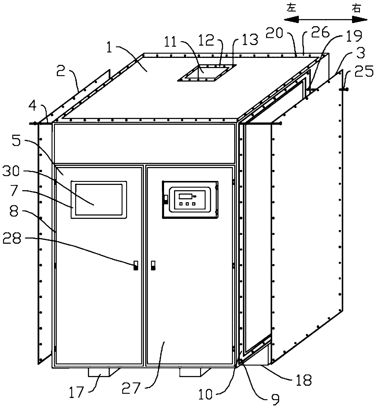
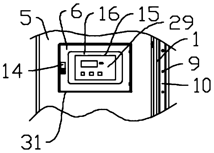
[0041] like figure 1 , 2 As shown, in this embodiment, the present invention includes:

[0042]Cabinet 1, openings are provided on the front, left and right side walls of the cabinet 1, a cavity for accommodating electrical components is provided in the cabinet 1 and the bottom of the cabinet 1 There is a cable sealing device fixed on the cable to achieve a waterproof effect; the bottom of the cabinet 1 is provided with a cable inlet hole, and the cable sealing device is arranged in the cable inlet hole for connecting the cable to the A seal is formed between the cabinets 1. The cable sealing device includes a shell, a cover plate and a sealing sleeve. The shell includes a shell main body, an extension body and a bottom plate. The inside of the shell main body is provided with a cavity that runs through its two ends. , the upper edge of the shell body extends outward evenly to form the epitaxial body, and the epitaxial body is perpendicular to the shell main body; the cable ...

Embodiment 2

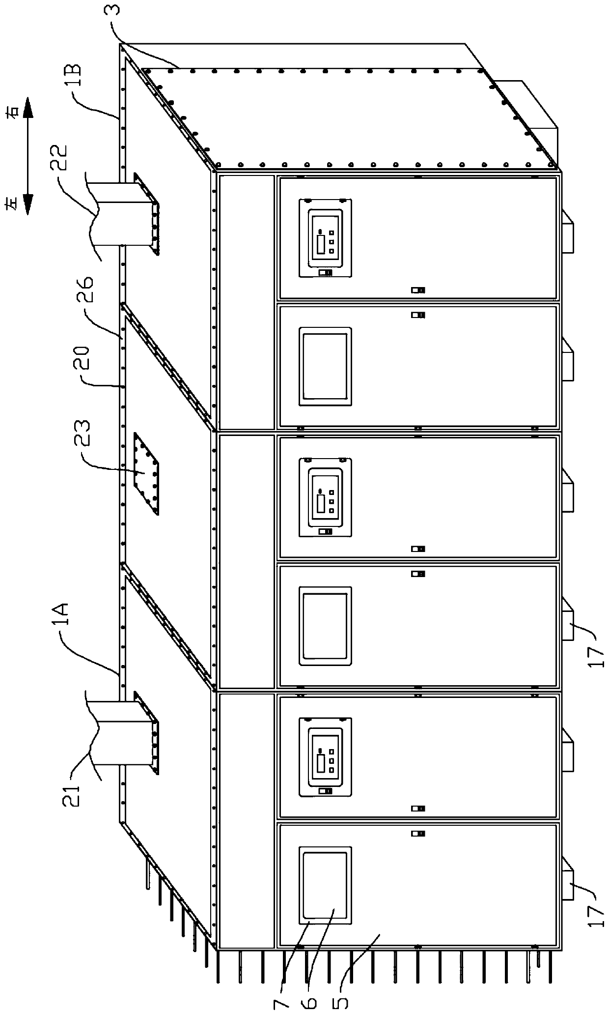
[0053] like image 3 As shown, in the present embodiment, there are three cabinet bodies 1 of the present invention, and the content other than that is the same as that of the first embodiment. The three cabinets 1 are respectively a cabinet 1A, a cabinet 1B and a cabinet 1C, and the cabinet 1A, the cabinet 1B and the cabinet 1C are sequentially connected in series to form a closed body, and the left sealing plate 2 passes through the fixed rod 4 and Fixing bolt 25 is fixed on the left side of described cabinet body 1C, and described right sealing plate 3 is fixed on the right side of described cabinet body 1A by fixing bar 4 and fixing bolt 25, and described forced air vent of described cabinet body 1C The air inlet pipe 21 is fixed at 11 places by bolts, the air outlet pipe 22 is fixed at the 11 places of the forced ventilation port of the cabinet 1A, and the forced ventilation port 11 of the cabinet body 1B is fixed with a blind Plate 23, through the air inlet pipe 18 and ...

Embodiment 3

[0055] like Figure 4 As shown, in this embodiment, there are four cabinets 1 of the present invention, and the content is the same as that of the first embodiment. The four cabinets 1 are respectively cabinet 1A, cabinet 1B, cabinet 1C and cabinet 1D, and cabinet 1A, cabinet 1B, cabinet 1C and cabinet 1D are sequentially connected in series to form a closed body, and the left The sealing plate 2 is fixed on the left side of the cabinet body 1D through the fixing rod 4 and the fixing bolt 25, and the right sealing plate 3 is fixed on the right side of the cabinet body 1A through the fixing rod 4 and the fixing bolt 25. The forced ventilation opening 11 of the body 1D is fixed with an air inlet pipe 21 by bolts, the forced ventilation opening 11 of the cabinet body 1A is fixed with an air outlet pipe 22 by bolts, and the forced ventilation opening 11 of the cabinet 1B is fixed with an air outlet pipe 22. A ventilation pipe 24 is arranged between the ventilation opening 11 and ...


PUM


Abstract

The invention relates to a waterproof transformer casing. The waterproof transformer casing comprises a cabinet body, wherein openings are formed in the side walls of the front side, the left side andthe right side of the cabinet body, and the cabinet body is internally provided with a cavity for accommodating electrical elements. A plurality of cabinet splicing holes and threaded holes A are formed in the circumferential direction at intervals in the side wall edge of the cabinet body, the cabinet splicing holes transversely penetrate through the cabinet body, and a left sealing plate for sealing the left side of the cabinet body and a right sealing plate for sealing the right side of the cabinet body are correspondingly arranged on the left side and the right side of the cabinet body. Fixing rods are arranged corresponding to the cabinet splicing holes in a one-to-one mode, fixing bolts and threaded holes A are arranged in a one-to-one corresponding mode, and the fixing rods sequentially penetrate through the left sealing plate, the cabinet splicing holes and the right sealing plate to separately fix the left sealing plate and the right sealing plate to the left side and the right side of the cabinet body. A left cabinet door and a right cabinet door are used for sealing the opening in the front side of the cabinet body, and a control panel is arranged on the inner side of the right cabinet door. A forcing ventilation opening is formed in the top of the cabinet body for forcing ventilation of the cavity inside the cabinet body. The cabinet body of the waterproof transformer casing can be waterproof and assembled meanwhile.

Description

technical field [0001] The invention relates to the technical field of substations, in particular to a waterproof transformer shell. Background technique [0002] With the application of various substations in various places, especially in enterprises, factories or companies that use high-voltage electricity, a large number of transformers will be used. Although enterprises or factories can prevent floods when considering site selection, with changes in the natural environment, some factories, enterprises or companies may still be attacked by floods, and transformers cannot better protect against floods. Penetration into the inside of the transformer shell will damage the internal components of the transformer shell, resulting in the loss of the company's assets. Secondly, if the floodwater seeps into the transformer shell, it will cause a power outage for the company. The inability of the transformer shell to work continuously underwater will cause the company to lack powe...

Claims


Application Information

Patent Timeline
Patent Type & Authority Applications(China)
IPC IPC(8): H01F27/02H01F27/08
CPCY02A30/14
Inventor 黄建国
Owner 黄建国
Why Eureka
Try Eureka