Cooling in a waveguide arrangement

A waveguide device and waveguide technology, applied in waveguide openings, waveguide devices, deicing/drying devices, etc.

Pending Publication Date: 2021-08-20
TELEFON AB LM ERICSSON (PUBL)
View PDF4 Cites 0 Cited by
  • Summary
  • Abstract
  • Description
  • Claims
  • Application Information

AI Technical Summary

Problems solved by technology

PCB includes signal interface for each waveguide

Method used


Image

  • Cooling in a waveguide arrangement
  • Cooling in a waveguide arrangement
  • Cooling in a waveguide arrangement

Examples


Embodiment Construction

[0036] The inventive concepts will now be described more fully hereinafter with reference to the accompanying drawings that illustrate certain embodiments of the inventive concepts. However, the inventive concept may be embodied in many different forms and should not be construed as limited to the embodiments set forth herein; rather, these embodiments are provided by way of illustration so that this disclosure will be thorough and complete, and incorporate the inventive concepts The range fully conveys to those skilled in the art. Throughout the specification, like symbols refer to like elements.

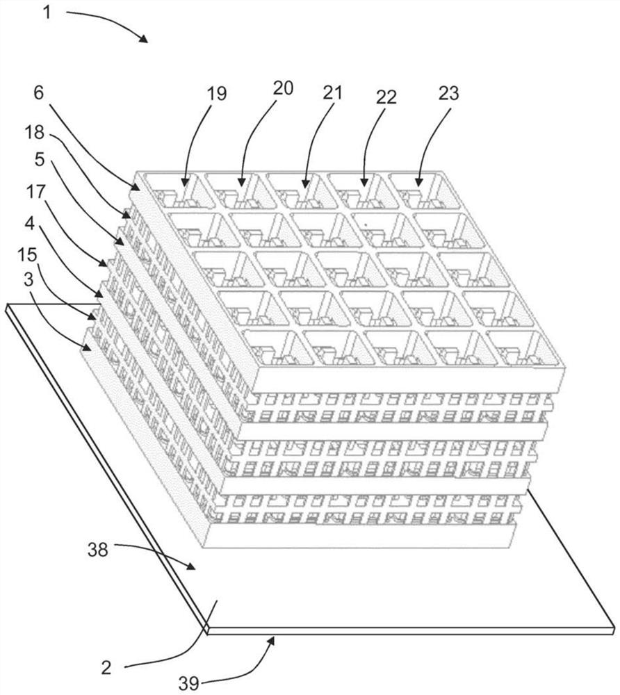
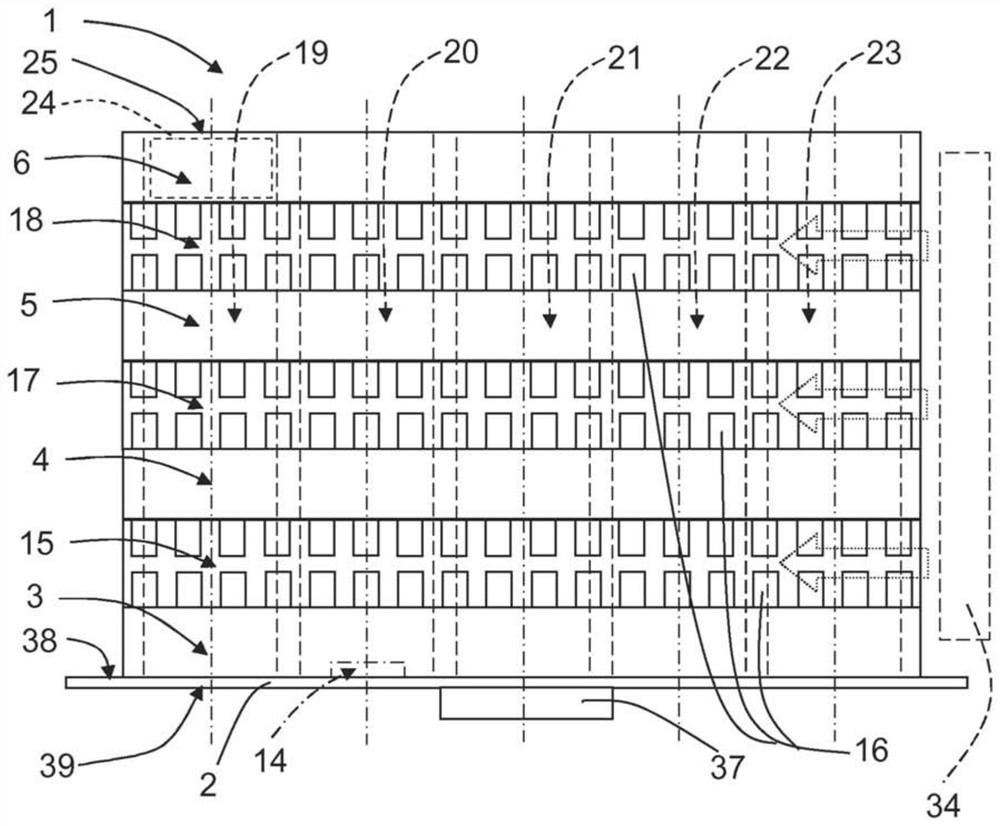
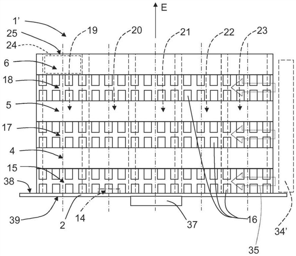
[0037] figure 1 A perspective side view of the waveguide device 1 is shown, Figure 2A shows a corresponding side view according to the first example and image 3 The corresponding top view is shown. Referring to these figures, a waveguide section 1 includes a mounting printed circuit board 2 (PCB), a bottom waveguide layer 3 on the PCB 2 , a first waveguide layer 4 , a second ...


PUM


Abstract

The present disclosure relates to a waveguide arrangement (1, 1') comprising a mounting printed circuit board (2), PCB, and at least a first waveguide layer (4). Each waveguide layer (3, 4, 5, 6) comprises at least a first waveguide conducting tube (7, 8, 9, 10, 11, 12), each waveguide conducting tube (7, 8, 9, 10, 11, 12) having an electrically conducting inner wall (13). The PCB (2) comprises a signal interface (14) for each waveguide conducting tube (7, 8, 9, 10, 11, 12). The waveguide arrangement (1, 1') further comprises at least a first coupling layer (15) that is positioned between the PCB and the first waveguide conducting tube such that at least the first waveguide conducting tube (7, 8, 9, 10, 11, 12) of the first waveguide layer (4) is connected to the corresponding signal interface (14) via the first coupling layer (15). Each coupling layer (15) comprises air passages (16, 16a, 16b) that enable air to pass through the coupling layer (15).

Description

technical field [0001] The present disclosure relates to a waveguide arrangement comprising a mounted printed circuit board (PCB) and at least a first waveguide layer. Each waveguide layer in turn includes at least a first air-filled waveguide, wherein each air-filled waveguide has a conductive inner wall. Background technique [0002] An antenna element is a device configured to transmit and / or receive electromagnetic signals (eg, radio frequency (RF) signals) for wireless communication. A phased antenna array is an antenna comprising multiple antenna elements with which the antenna radiation pattern can be controlled by varying the relative phase and amplitude of the signals fed to the different antenna elements. [0003] The practical realization of the signal filtering function of such antenna elements is a challenging task. High Q factors, multiple resonators, and high precision are required to achieve filters with low loss and strong rejection of frequencies near the...

Claims


Application Information

Patent Timeline
Patent Type & Authority Applications(China)
IPC IPC(8): H01Q1/02H01Q21/06H01P1/30H01Q21/00H01Q13/06
CPCH01P1/30H01Q21/0087H01Q13/06H01Q1/02H01Q21/064H01Q13/02H01Q13/0233
Inventor 阿纳托利·德伦尼夫珀尔·因戈尔海格彼得·梅林
Owner TELEFON AB LM ERICSSON (PUBL)
Why Eureka
Try Eureka