Partially-enhanced extended finite element method of crack tip unit

A technology of extended finite element and crack tip, which is applied in the field of extended finite element with partly enhanced crack tip unit, which can solve problems such as difficulty and inconvenient grid division, and achieve the effect of accurate calculation results

Active Publication Date: 2020-03-06
HEFEI GENERAL MACHINERY RES INST +1
View PDF4 Cites 7 Cited by
  • Summary
  • Abstract
  • Description
  • Claims
  • Application Information

AI Technical Summary

Problems solved by technology

If only the jump function is used, the crack tip needs to be located on the cell boundary. This restriction has caused great inconvenience to the mesh division, especially when the crack propagates and the crack morphology changes, it is necessary to ensure that the crack tip is always located on the cell boundary. , very difficult

Method used


Image

  • Partially-enhanced extended finite element method of crack tip unit
  • Partially-enhanced extended finite element method of crack tip unit
  • Partially-enhanced extended finite element method of crack tip unit

Examples


Embodiment Construction

[0025] In this embodiment, a flat tensile model with cracks is used, such as Figure 7-a As shown, a tensile load σ=1Mpa is applied to the upper surface of the model, the bottom edge is the foot support, and the left bottom foot is the fixed support. Height H=2mm, crack length a=0.3mm, plate width b=1mm, material properties: Young's modulus E=1×10 3 Mpa, Poisson's ratio υ=0.3. Assume that the plate is in a plane strain state.

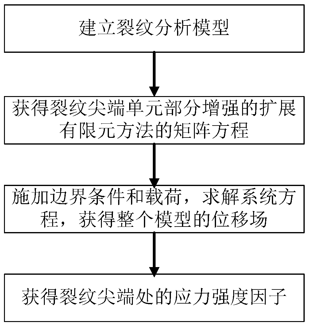
[0026] Such as figure 1 As shown, this embodiment is calculated using the extended finite element method enhanced by the cutting-edge element part, and the main steps are as follows:

[0027] S1, establishing a crack analysis model;

[0028] The specific steps are as follows:

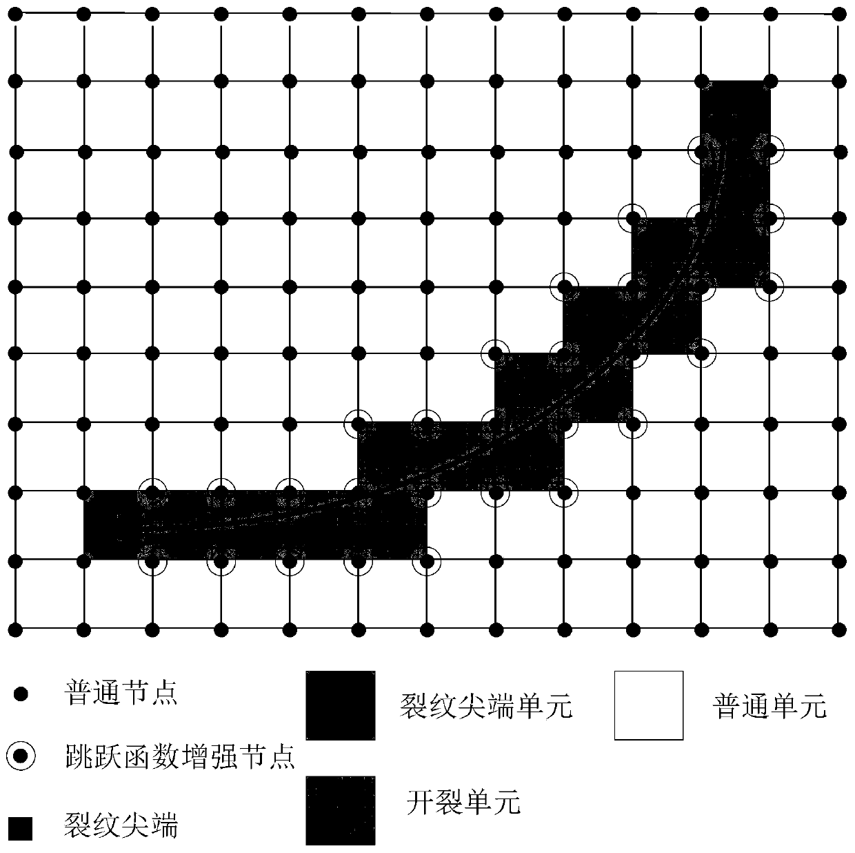
[0029] S11. Carry out grid division on the geometric area and divide it into several units; in this scheme, it is divided into two different grid division schemes, such as Figure 7-b As shown, the layout of graph nodes is 22×42, which is the grid graph used by XFEM-P. Fi...


PUM


Abstract

The invention relates to the field of fracture mechanics, in particular to a partially-enhanced finite element expansion method of a crack tip unit which comprises the following steps: S1, establishing a crack analysis model; S2, obtaining a matrix equation of partially-enhanced extended finite element method of the crack tip unit; S3, applying boundary conditions and loads, solving a system equation and acquiring a displacement field of a whole model and S4, on the basis of obtaining the displacement field, obtaining a stress intensity factor at crack tips by adopting a cross-phase integral method. The method has the advantages that the crack tip unit adopts a partially enhanced displacement field, and the enhanced displacement field is adopted for a crack tearing part to simulate the displacement discontinuity of a crack surface; for an untorn part, a finite element continuous displacement field is adopted, and simulation of displacement field characteristics of the crack tip unit can be achieved.

Description

technical field [0001] The invention relates to the field of fracture mechanics, in particular to an extended finite element method for crack tip element partial reinforcement. Background technique [0002] Damage to materials and structures can cause accidents and even huge loss of life and property. Many damages to materials and structures are caused by the existence of cracks. In order to reduce the damage to materials or structures caused by cracks, fracture mechanics came into being. Numerical methods have become an indispensable tool in the analysis of fracture mechanics. Commonly used numerical methods for fracture mechanics include singular element method, smooth finite element method, and extended finite element method. [0003] Among these methods, the singular element method and the smooth finite element method are used to simulate the crack surface displacement discontinuity by the repeated node method. When meshing, the crack is located at the cell boundary, an...

Claims


Application Information

Patent Timeline
Patent Type & Authority Applications(China)
IPC IPC(8): G06F30/23G16C60/00G06F111/10G06F119/14
CPCG16C60/00Y02T90/00
Inventor 江勇范志超陈学东聂德福
Owner HEFEI GENERAL MACHINERY RES INST
Why Eureka
Try Eureka