
Wiring harness binding device for conveniently fixing electronic controller wiring harness

An electronic controller and wire harness technology, which is applied in the manufacture of wire harnesses, cable installation, cable installation devices, etc., can solve the problems of wire harness falling off, affecting the quality of the bundle, and the wire harness cannot be fixed, so as to achieve firm binding and convenient storage. Effect

Active Publication Date: 2020-03-06
徐州思达新技术开发有限公司
View PDF11 Cites 5 Cited by
  • Summary
  • Abstract
  • Description
  • Claims
  • Application Information

AI Technical Summary

Problems solved by technology

[0004] The purpose of the present invention is to provide a wire harness binding device for conveniently fixing the wire harness of the electronic controller, so as to solve the problem that the existing binding device proposed in the above background technology cannot fix the wire harness before the wire harness is bound, and the wire harness is in the process of bundling It is easy to fall off from the device, which affects the normal operation of the device, and the binding between the wire harnesses is not firm, which affects the quality of the bundle, and at the same time, the bundled wire harnesses cannot be centrally stored and processed

Method used


Image

  • Wiring harness binding device for conveniently fixing electronic controller wiring harness
  • Wiring harness binding device for conveniently fixing electronic controller wiring harness
  • Wiring harness binding device for conveniently fixing electronic controller wiring harness

Examples


Embodiment Construction

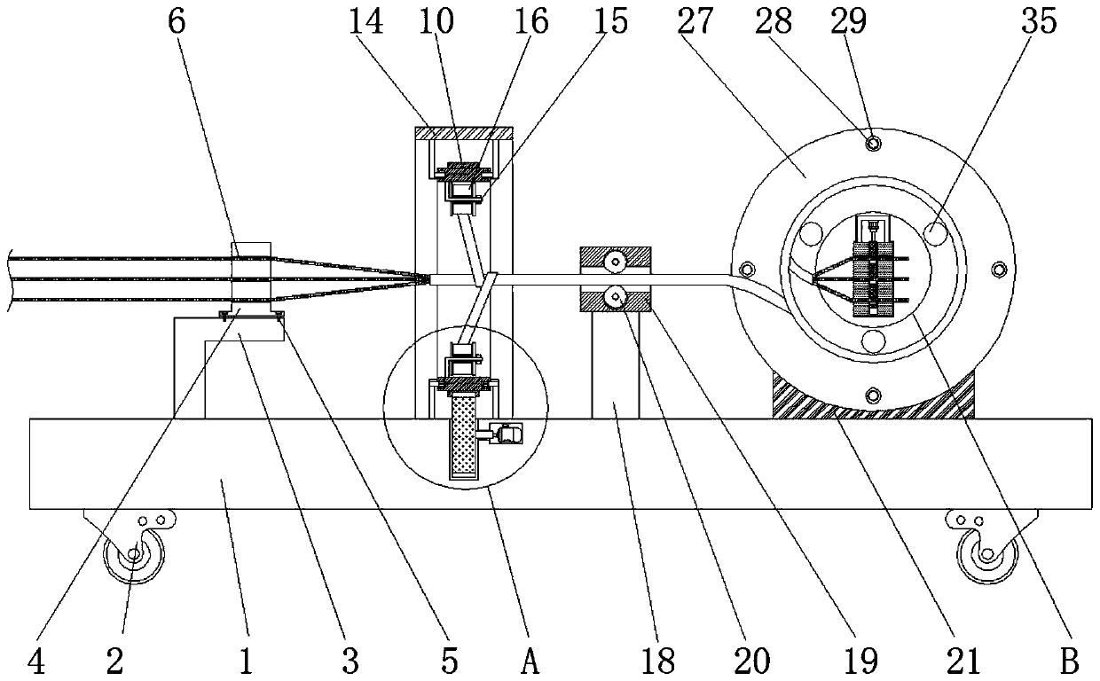
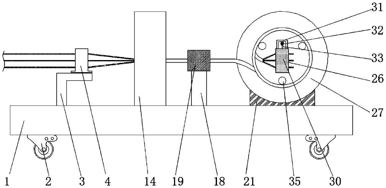
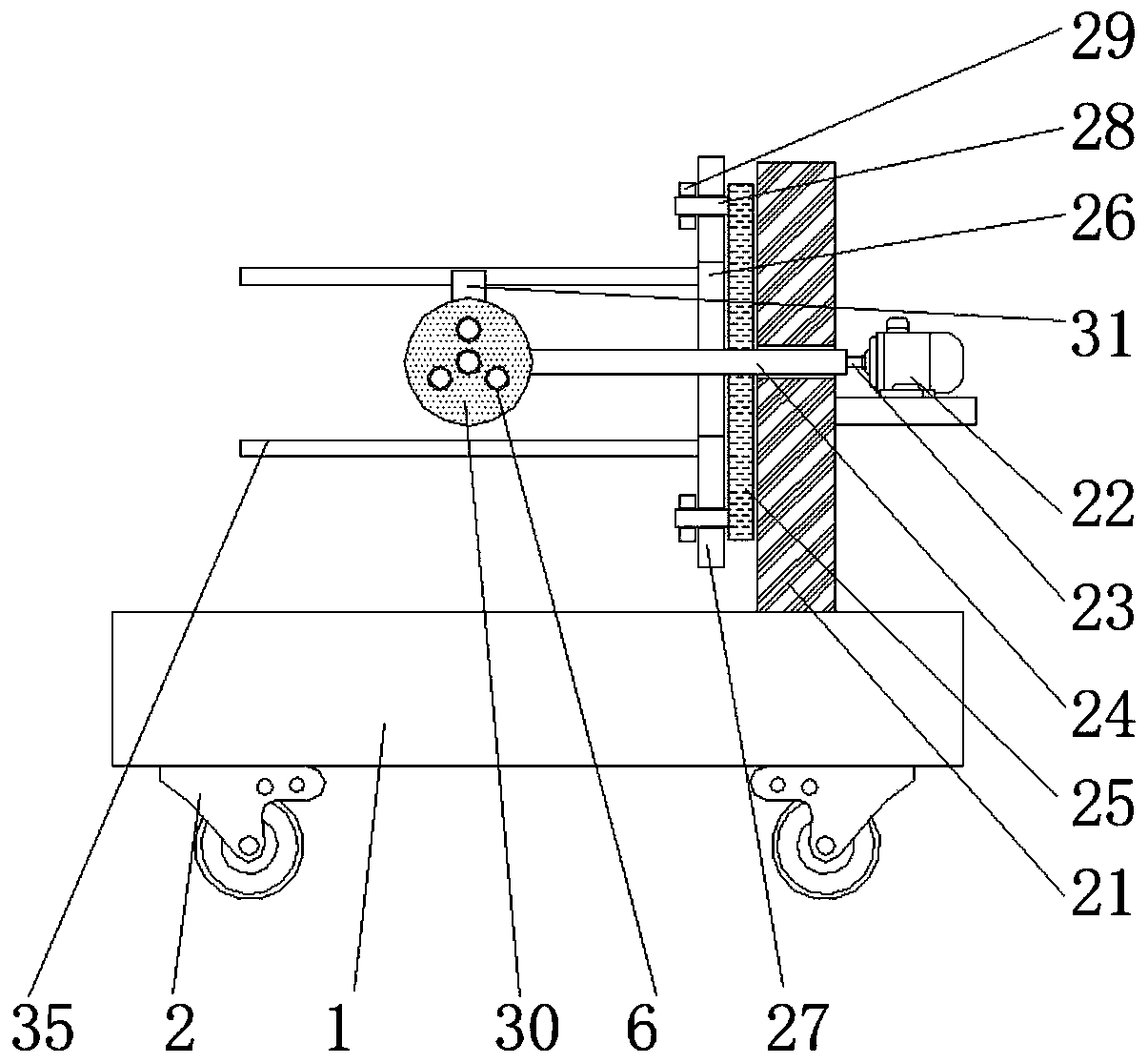
[0028] The technical solutions in the embodiments of the present invention will be clearly and completely described below in conjunction with the accompanying drawings in the embodiments of the present invention. Obviously, the described embodiments are only a part of the embodiments of the present invention, rather than all the embodiments. Based on the embodiments of the present invention, all other embodiments obtained by those of ordinary skill in the art without creative work shall fall within the protection scope of the present invention.

[0029] See Figure 1-7 , The present invention provides a technical solution: a wire harness binding device that is convenient to fix the electronic controller wire harness, according to figure 1 with figure 2 As shown, the bottom left and right sides of the base 1 are provided with self-locking rollers 2, and the left side of the upper end surface of the base 1 is fixed with a first carrier 3, the first carrier 3 is provided with a firs...


PUM


Abstract

The invention discloses a wiring harness binding device for conveniently fixing an electronic controller wiring harness. The wiring harness binding device includes a base, a first motor, and a third carrier. A first roller is rotatably connected to a bracket. A support rod is fixed inside a gear ring. A first carrier and the third carrier are disposed on the left and right sides of the second carrier, respectively. A fourth carrier is disposed on the right side of the third carrier. A rotating rod is rotatably connected to the fourth carrier. A stopping plate is disposed on the front side of the fixing plate. A carrying disk is fixed to the front side of the rotating rod. A hydraulic cylinder is fixed on the inner top of a second rack. A bobbin is disposed outside the carrying disk. According to the wire harness binding device for conveniently fixing the electronic controller wire harness, after the head end of the wire harness passes through a moving column, the moving column can be moved downward under the effect of the hydraulic cylinder and a hydraulic rod. At this time, the contact portion of the wire harness and the moving column is bent downward, so that the head end of thewire harness is stably caught in the carrying disk.

Description

Technical field [0001] The present invention relates to the technical field related to electronic controllers, in particular to a wire harness binding device for facilitating fixing the electronic controller wire harness. Background technique [0002] The electronic controller is an important electronic product component, which is widely used in electronic production and plays a very important role in people’s daily life. The electronic controller is a miniature computer management center. Calculating, analyzing and judging, and determining countermeasures as input, and then issuing control instructions and directing the actuator to work as output. Its core is a microcomputer system with a single-chip microcomputer as the main body. The electronic controller needs to bind the wiring harness on it when using it. , To prevent excessive accumulation of wire harnesses and affect the normal operation of the electronic controller, and the binding device needs to be used in the process ...

Claims


Application Information

Patent Timeline
IPC IPC(8): H01B13/012H02G1/00G06F1/18
CPCG06F1/18H01B13/01272H02G1/00
Inventor 李享李黎明
Owner 徐州思达新技术开发有限公司
Learn More