A high-efficiency heat dissipation type transformer device for thermal power generation

A transformer and heat-dissipating technology, applied in the field of high-efficiency heat-dissipating transformers for thermal power generation, can solve the problems of shortening the service life of the transformer, failing to work normally, causing accidents, etc., and achieving the effect of improving the heat-dissipating performance.

Inactive Publication Date: 2020-12-15
阳城国际发电有限责任公司
View PDF10 Cites 0 Cited by
  • Summary
  • Abstract
  • Description
  • Claims
  • Application Information

AI Technical Summary

Problems solved by technology

For the needs of anti-corrosion and explosion-proof, transformers are generally installed in a closed cabinet. During the working process of transformers, electronic components will generate a lot of heat. If it is not released in time, the temperature inside the transformer will rise, which may cause the transformer to not work normally and shorten the service life of the transformer. Necessary loss, the heat dissipation effect of the oil-immersed or air-cooled methods currently on the market is not ideal
[0003] Chinese patent (notification number CN209103897U) discloses a high-efficiency heat dissipation transformer used in thermal power plants. Although it can be cooled by air-cooled liquid cooling, it has defects in the specific air-cooled liquid-cooled structural design and heat dissipation performance. and deficiency

Method used


Image

  • A high-efficiency heat dissipation type transformer device for thermal power generation
  • A high-efficiency heat dissipation type transformer device for thermal power generation
  • A high-efficiency heat dissipation type transformer device for thermal power generation

Examples


Embodiment 1

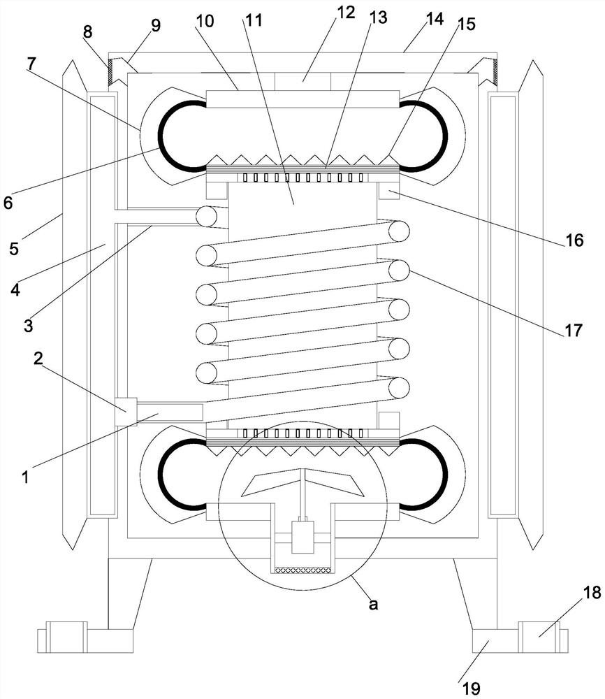
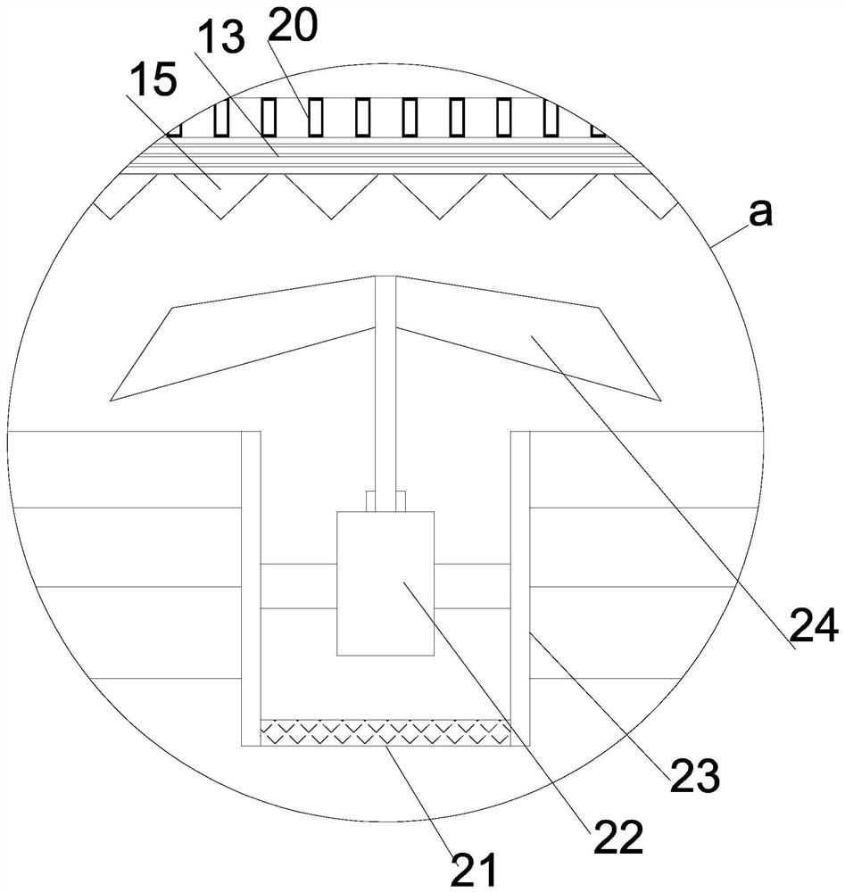
[0022] see Figure 1~4 , in an embodiment of the present invention, a high-efficiency heat-dissipating transformer device for thermal power generation, including a vertically arranged support installation cover 14, a transformer main body 11 is vertically arranged at the inner middle position of the support installation cover 14, and the support installation cover 14 The lower end is provided with a bending mounting plate 19 at equal angles, and fixed mounting holes 18 are arranged on the bending mounting plate 19. The upper and lower ends of the transformer main body 11 are provided with a limit mounting cylinder 16, facing the support cover of the limit mounting cylinder 16. A fixed installation plate 10 is arranged horizontally inside, and a heat conduction plate 13 is arranged horizontally on the side of the limit installation cylinder 16 facing the fixed installation plate 10, and a number of arc-shaped heat conduction plates are arranged at equal angles between the heat c...

Embodiment 2

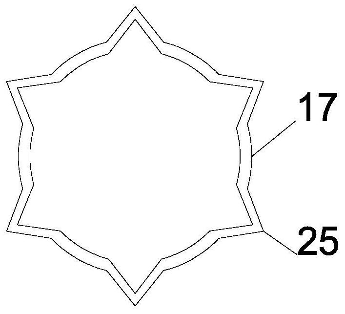
[0025] On the basis of Embodiment 1, since multiple sets of heat pipes 20 point contact for heat conduction, the speed of heat conduction is significantly improved, and the heat conduction protrusions 25 on the heat conduction pipe 17 will significantly increase the heat conduction area, and the sub-cooling process cooperates with liquid cooling to dissipate heat , so that the thermal effect is significantly improved.


PUM


Abstract

The invention relates to the field of power equipment, in particular to an efficient heat dissipation type voltage transformation device for thermal power generation. The efficient heat dissipation type voltage transformation device comprises a vertically arranged support mounting cover, a transformer main body is vertically arranged in the middle of the interior of the support mounting cover, bent mounting plates are arranged at the lower end of the support mounting cover at equal angles, fixed mounting holes are formed in the bent mounting plates, limiting mounting cylinders are arranged atthe upper end and the lower end of the transformer main body, and fixed mounting plates are horizontally arranged in the support cover directly facing the limiting mounting cylinders. Through a multi-point contact rapid heat conduction structure and cooperation of multiple sets of cooling fins, cooling plates and heat conduction plates, the heat conduction performance of the device is excellent; meanwhile, bottom up-flow type cooling is carried out, so heat can be quickly discharged from the device; through a spiral flow guide type liquid cooling structure, two kinds of heat dissipation are carried out at the same time, the heat dissipation performance of the device is remarkably improved, and the transformer can continuously, stably and efficiently operate.

Description

technical field [0001] The invention relates to the field of power equipment, in particular to a high-efficiency heat dissipation type transformer for thermal power generation. Background technique [0002] Transformer is a device that uses the principle of electromagnetic induction to change AC voltage. The main components are primary coil, secondary coil and iron core. The main functions are: voltage conversion, current conversion, impedance conversion, isolation, voltage stabilization, etc. The main transformers used in thermal power plants are step-up transformers, whose main function is to boost the electricity generated by the generator to the grid voltage, and then merge the generated electricity into the grid. For the needs of anti-corrosion and explosion-proof, transformers are generally installed in a closed cabinet. During the working process of transformers, electronic components will generate a lot of heat. If it is not released in time, the temperature inside ...

Claims


Application Information

Patent Timeline
Patent Type & Authority Patents(China)
IPC IPC(8): H01F27/08H01F27/10H01F27/16H01F27/22H01F27/06
CPCH01F27/06H01F27/08H01F27/085H01F27/10H01F27/16H01F27/22
Inventor 魏洋洋
Owner 阳城国际发电有限责任公司
Why Eureka
Try Eureka